Incident Energy Devices Under 125A Calculator Guide (Level 3)
What is it?
This incident energy calculator gives very quick results for circuits that are fed from low voltage HRC fuses and miniature circuit breakers (MCB) up to a rating of 125 amperes that are in common use within Europe. It is based upon IEEE 1584:2018 Guide for Performing Arc Flash Hazard Calculations. More information can be found in Chapter 4: Prediction and Chapter 14: Hazard and Severity Calculators.
Why would you use it?
Risk assessment is the bedrock of this guide in managing the arc flash hazard. Chapter 3: Risk Assessment and the 4P Guide explains that the first step is predicting the hazard severity and a calculation of the incident energy will allow you to determine the thermal effects of a possible arcing event.
Most fuses and circuit breakers that are 125 amperes or less in Europe provide protection against arcing faults, but care is required as there can be fairly high levels of incident energy even below ratings of 125 amperes. As has been expressed previously throughout this guide, it is usually because of high source impedance meaning that there is not enough prospective short circuit current to operate the protective device instantaneously. In these cases, the device sees the fault as being an overload which will take time to clear and as incident energy is directly proportional to time, there can be a high release of thermal energy in an arc before the fault is automatically disconnected from the supply. However, in most cases, the types of devices that are commonly used in final circuits can disconnect safely and without damage providing that there is enough prospective short circuit current (PSCC) to operate the protective device instantaneously.
This calculator allows you to determine the incident energy for when the listed devices are operating in the instantaneous region and also where the device operates outside this region. You do not need to have a time current curve or exact knowledge of the fault current providing that you know that it is not below the instantaneous threshold. This gives an option to manage by exception and be able to discount smaller circuits where they fit the criteria. This allows more focus to be made on higher power circuits which often make up only 10 to 20% of circuits on typical industrial and commercial systems.
Where would you use it?
The calculator is most useful where there is limited information about the system to be worked upon or in proximity to. The calculator has limitations; it cannot be applied to every situation, is suitable for systems having:
- Voltage levels of 400 volts harmonised in Europe.
- Frequencies of 50 or 60 Hz.
- Bolted fault current (Prospective Short Circuit Current) up to 80kA but no greater than the fault rating of the protective device.
- Working Distances between 305mm and 900mm.
- Grounding of all types and Ungrounded.
- Equipment enclosure size 508 x 508 x 508mm.
- Gaps between conductors: 32mm only.
- Faults involving three phases only.
- AC (Alternating Current) Faults only.
How do you use it?
The following sets out how a competent electrical engineer can use the calculator to arrive at an incident energy level at a stated working distance. The calculator tool follows the principle that a calculation is made to determine the minimum fault current to operate a circuit breaker or fuse instantaneously. The screen shot of the actual calculator is shown in Figure 14.15. The devices are the most common types in use which include the DIN NH and BS 88 types of high rupturing capacity fuses and miniature circuit breaker to EN 60898 and EN 61009-2.
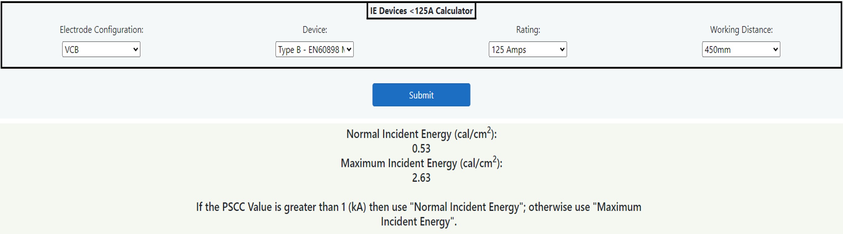
Figure 14.15 IE Devices <125A Calculator
The fields on the data entry and output form are as follows.
Electrode Configuration
There are five different electrode configurations, and this field is a dropdown list giving choices as follows:
- VCB: Vertical conductors/electrodes inside a metal box/enclosure.
- VCBB: Vertical conductors/electrodes terminated in an insulating barrier inside a metal box/enclosure.
- HCB: Horizontal conductors/electrodes inside a metal box/enclosure.
- VOA: Vertical conductors/electrodes in open air.
- HOA: Horizontal conductors/electrodes in open air.
Chapter 8: Data Collection describes which electrode configuration to use as the choice will determine not only the arcing current but also the incident energy. An assumption of 508 x 508 x 508 mm enclosure size and an arc gap of 32mm has been made.
Device
A dropdown list menu gives a choice between DIN NH and BS 88 types of high rupturing capacity fuses and three phase miniature circuit breakers to EN 60898 and EN 61009-2.
Rating
A dropdown list menu gives a choice between the range of 32 amperes up to 125 amperes.
Working Distance
A dropdown list menu gives a choice between 305mm, 450mm, 600mm and 900mm from a possible arcing source and the torso and head. Be aware that the hands can be closer to an arcing source.
Normal Incident Energy (cal/cm2) (CALCULATED)
This gives a value of incident energy for the configuration, working distance and rating chosen above where the PSCC is high enough to allow instantaneous operation of the device.
Maximum Incident Energy (cal/cm2) (CALCULATED)
This gives a value of incident energy for the configuration, working distance and rating chosen at or below the value of PSCC that would be required to allow instantaneous operation of the device. A two second disconnection time* has been applied.*NOTE: The IEEE 1584:2018 Guide states “If the total protective device clearing time is longer than two seconds, consider how long a person is likely to remain in the location of the arc flash. It is likely that a person exposed to an arc flash will move away quickly if it is physically possible, and two seconds usually is a reasonable assumption for the arc duration to determine the incident energy.”
If the PSCC value is greater than XX (kA) then use “Normal Incident Energy”; otherwise use “Maximum Incident Energy” (CALCULATED)
The value shown by “XX (kA)” where "XX" is replaced by a value, is the prospective short circuit current above which will operate the protective device instantaneously. If the PSCC is equal or less than this given value, then use the value given by “Maximum Incident Energy”; otherwise use “Normal Incident Energy”.Conditions and Assumptions
You are advised to check that these are reasonable assumptions:
- That the device capacity is not exceeded by the maximum value of PSCC (strength and capability).
- Based on clearance curves generic device types from Amtech software.
- 508 x 508 x 508mm enclosure size.
- 32 mm gap between conductors.
- No motor contribution considered.
- The reported incident energy figures are found by rounding up in 0.25kA segments.
- 400 volts systems only.
- Instantaneous trip times considered are a full cycle 20ms for MCBs and a half cycle of 10ms for fuses at 50 Hertz.
- Highest PSCC considered is 15kA for MCBs and 80kA for fuses.