IDMT Relay Time Current Curve Calculator Guide
What is it?
The generic Inverse Definite Minimum Time (IDMT) time current curve calculator will allow you to not only produce curves for standard IEC and IEEE relay characteristics but will give a trip time for a given arcing current.
Why would you use it?
By using the calculator, a time for operation can be provided for a specific arcing current input. This can be used in the incident energy calculators where a time to trip is required. There is a specific curve produced for the input time multiplier but also a range of curves for time multiplier settings between 0.05 and 1. This may help in considering alternative settings.
Where would you use it?
The calculator can be used wherever IDMT curves are used which are normally but not exclusively in high voltage equipment. The limitations are:
- IEEE moderately, very, and extremely inverse curves.
- IEC standard, very, extremely, and long-time inverse curves.
- Current multiplier from 0.5 to 2 in steps of 0.05.
- Time multipliers from 0.05 to 1.
- Relay operation time only, user to add allowances for error and switchgear operation time.
How do you use it?
The standard IDMT overcurrent characteristics are expressed as a mathematical formula according to the IEC 60255-3/BS142 and IEEE C37.112-1996 standards and are often the basis of the electromechanical time current curves. The fact that the curves are based on a mathematical formula makes it easy to sense check the relay settings and of course electronic relays use the same curves.
The equation for operating time from IEC 60255 trip curves is as follows:
| t(I) = TMS | { |
|
} |
Where, Is = the current setting and I = the actual current and k and α are the curve type constants. See table below.
There are four curve types used in IEC 60255 which are: standard inverse, very inverse, extremely inverse and long time standard inverse. For electromechanical relays, the curves are fixed for the particular relay model. So, in other words, if a standard inverse function is required then that is built into the specification of the relay. It will be necessary therefore to check the relay model with manufacturer’s data to determine the curve type.
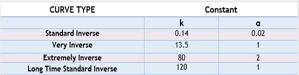
Table 14.30 IEC Curve Constants
Note that US relay characteristics to ANSI and IEEE follow a similar format to the above equation but have a further constant B which is added to the expression.
The equation for operating time from IEEE C37.112-1996 trip curves is as follows:
| t(I) = TD | { |
|
+ B | } |
Where, Is = the current setting and I = the actual current and A, B and p are the curve type constants. TD stands for time dial and is often referred to as a time dial multiplier or TDM. The relationship is as follows:
| TDM = |
|
See the below table.
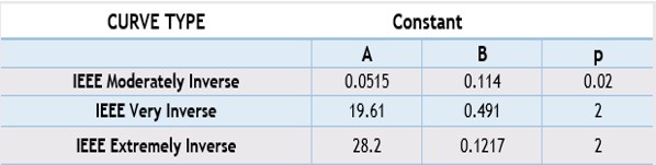
Table 14.31 IEEE Curve Constants
The following is a description of the user entry and calculation field given in the image of the IDMT time current curve calculator given in Figure 14.32.
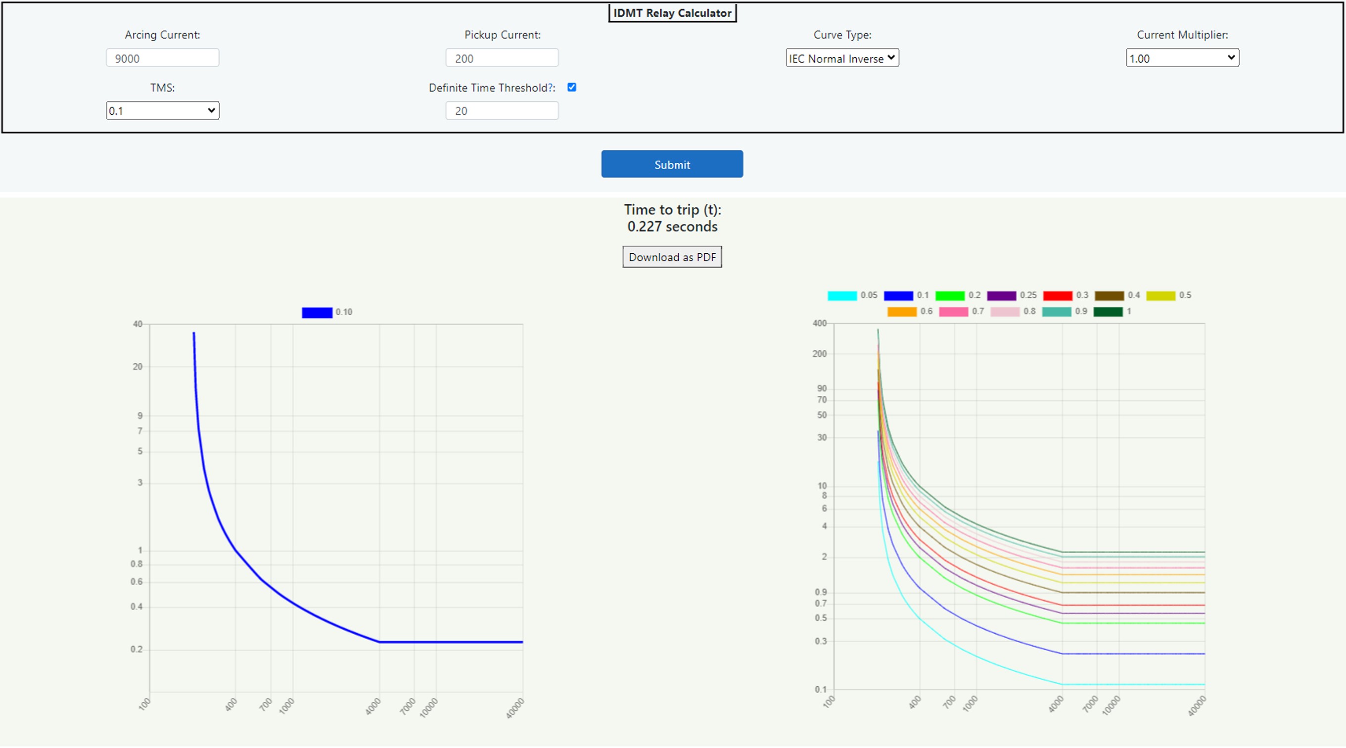
Figure 14.32 IDMT Relay Time Current Curve Calculator
Pickup current (Is)
This is the value at which the relay will start to operate and is usually the current transformer primary turns ratio. So, if this is 400/5 for instance, enter 400. This does of course assume that the relay matches the secondary winding of the current transformer.
Curve Type
Choose from the drop-down menu from the following options. IEC standard inverse, IEC very inverse, IEC extremely inverse, IEC long time standard inverse IEEE moderately inverse, IEEE very inverse and IEEE extremely inverse.
Current Multiplier (x Is) (Range: from 0.5 to 2 in 0.05 intervals)
Enter a value that corresponds with the relay setting. For instance, if the relay is a static, digital, or numerical type of relay this can be obtained directly from the relay setting sometimes via slider switches or digital readout. So, a current multiplier of 1 will be the pickup current x 1 or 100%. For electro-magnetic relays the detail can be obtained from the plug bridge and the tapping range is usually 50%, 75%, 100% (For a 5-ampere relay, 100% means 5A), 125%, 150%, 175% and 200%. Some manufacturers may use 1.5, 3.5, 5, 6.25, 7.5, 8.75 and 10A. For example, for a CT rating of 100/5A, if the relay is set to operate at 5A then the plug setting will be equal to relay current setting/5A = 5A/5A = 1 or 100%. For a relay to operate at 2.5A, the plug setting (for this example) will be 2.5A/5A = 0.5 or 50%.
TMS (Time Multiplier Setting)
Choose from the drop-down list from between 0.05 and 1. For static, digital, or numerical type of relay this can be obtained directly from the relay setting sometimes via slider switches or digital readout. For electro-magnetic relays, the detail can be obtained from the time dial on the front of the relay, this is shown in Chapter 8: Data Collection section 8.4.2 Electromechanical Inverse Definite Minimum Time Relays.
Definite Minimum Time
This field gives the ability to apply a definite minimum time for operation of the relay when the checkbox is checked. Different relays give a different threshold for minimum time for operation which, when stated, are usually at 10 to 40 times the pickup current as adjusted by the current multiplier. So, for instance, if the pickup current is 100 amperes, the current multiplier is 2 and the definite time threshold is 20, then the curve will follow the relay curve characteristic up to 4000 amperes (100 x 2 x 20). Above that threshold, the time to trip will remain static or in other words a definite minimum time for operation. There will be no definite time for operation if the checkbox is left unchecked, when this is the case, the field will be greyed out and display as "NA".The effect of the current multiplier, the time multiplier setting, and definite time threshold can be shown in Figure 14.33 below. So, in this example, the pickup current is 100 amperes, the current multiplier is 2 and the definite time threshold is 20. So, the set pickup is 200 amperes (100 x 2) and the definite time threshold is 4000 amperes (200 x 20).
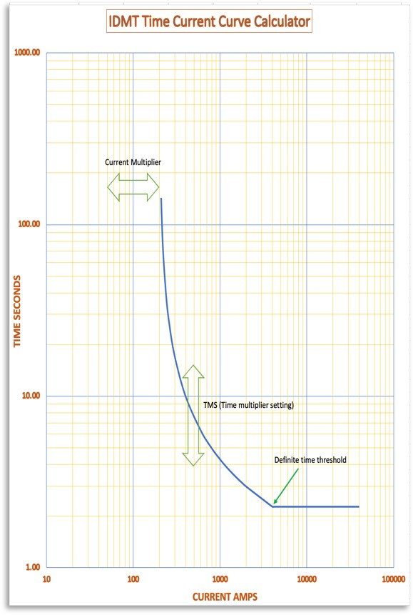
Figure 14.33 IDMT Relay Effect of Settings
Arcing Current
Enter the arcing current from the IEEE 1584 incident energy calculator both for actual and reduced values. Clearly, the arcing current must be greater than the pickup current as adjusted by the current multiplier for the relay to operate.
Outputs
A time current curve for the full range of time multiplier settings will be displayed for the relay data entered when the submit button is selected. Curves can be deselected by clicking on the associated colour block at the top of the graph. In addition, a time to trip based upon the arcing current given will be displayed. The arcing current can be changed to consider the minimum arcing current from the IEEE 1584 incident energy calculator to take account of possible increased trip times.Allowance for Relay Error and Switchgear Operating Time
Do not forget the relay error and switchgear operating time. Trip times are made up of relay reaction time + trip coil delay time + circuit breaker mechanism operating time. All relays have errors in timing which have to be declared if manufactured and tested in accordance with IEC 60255. We must also factor in the time for operation of the switchgear. This again can be obtained from manufacturer’s data, commissioning, or timing tests but as a guide for the purposes of an arc flash calculation a generic allowance can be built in. A table of allowances and generic switchgear operating times are given in Chapter 8: Data Collection.