DC Arc Flash Calculator Guide (Level 1)
What is it?
This incident energy calculator gives very quick results for Direct Current (DC) applications. It is based upon several papers that have addressed the calculation of incident energy in direct current systems, see references at the end of these instructions. This calculator allows you to determine the incident energy at a working distance in cal/cm2 for enclosed and open arcs. Further information is available in Chapter 14: Hazard and Severity Calculators.
Why would you use it?
Risk assessment is the bedrock of this guide in managing the arc flash hazard. Chapter 3: Risk Assessment and the 4P Guide explains that the first step is predicting the hazard severity and a calculation of the incident energy will allow you to determine the thermal effects of a possible arcing event.
Where would you use it?
The calculator is based upon published white papers and so does not carry the same weight as IEEE 1584:2018. As such it can be used as a guide with good engineering judgement applied in respect of input values and results. The calculator has limitations; it cannot be applied to every situation, is suitable for systems having:
- Voltage range 50 volts to 30,000 volts.
- Direct Current only.
- Working Distances between 305 mm and 900 mm.
- Grounding of all types and Ungrounded.
- Gaps between conductors: 1 to 250 mm.
How do you use it?
The following sets out how a competent electrical engineer can use the calculator to arrive at an incident energy level at a stated working distance.
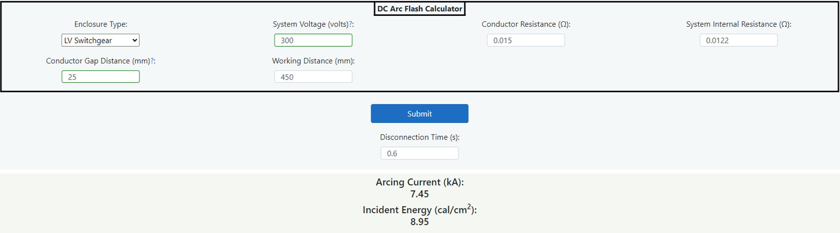
Figure 14.16 DC (Direct Current) Incident Energy Calculator
Figure 14.16 shows the dashboard from the DC incident energy calculator. An enclosure type or open air is selected form the dropdown field and this will require values for the internal resistance of the source, the conductor resistance and the arc gap. The Arcing Current Idc arc is then shown which can be used to determine the disconnection time from the TCC and entered into the disconnection time t. If this is not available or there is not a device in circuit, a value can be entered which is an estimate of reaction time. Finally, a working distance d is entered which is measured to the source of the arc.
(Note, the IEEE 1584 Guide uses a figure of two seconds if there is no restriction of access).
The calculated incident energy, which is shown, depends upon the type of enclosure (or air) distance and disconnection time given the electrical system parameters.
The entry and output field are listed as follows:
Enclosure Type
Choose from a dropdown menu as described in Table 14.18 below.
System Voltage (volts)
Enter DC (Direct Current) open circuit volts.
Conductor Resistance (Ω)
Enter the total conductor resistance from the source to the equipment in ohms.
System Internal Resistance (Ω)
Enter the internal resistance of the system or source in ohms.
Conductor Gap Distance (mm)
Enter the gap between conductors in mm.
Working Distance (mm)
The distance between the potential arc source (not just the front of the panel) and the face and chest of the worker.
DC Arcing Current Iarc (kA)
The calculated DC arcing current.
Submit Button (Clarification)
Press the submit button after the above data has been entered and this will return an arcing current Iarc and a reduced arcing current Iarc_min providing there are no invalid entries. After this you can determine an appropriate disconnection time to use for the upstream device to operate after which you would press the submit button again to ascertain the incident energy and arc flash boundary levels for this configuration.
Disconnection Time (seconds)
This is the time to clear the DC arcing current Iarc and is obtained from the time current curve of the upstream protective device.
Incident Energy (cal/cm2)
The calculated dc incident energy at the working distance.Calculation Method
If we take a simple DC circuit which is subject to an arc fault, the current that flows in the arc is found by application of ohms law which is I = V/R. So, the source voltage is divided by the sum of the series impedances made up of the; source resistance Rs, system (or conductor) resistance Rc and the arc resistance Rarc.
To find the arc resistance Rarc we apply the following equation:
| Rarc = |
|
Where G = conductor gap in mm and Iarc = DC arcing current.
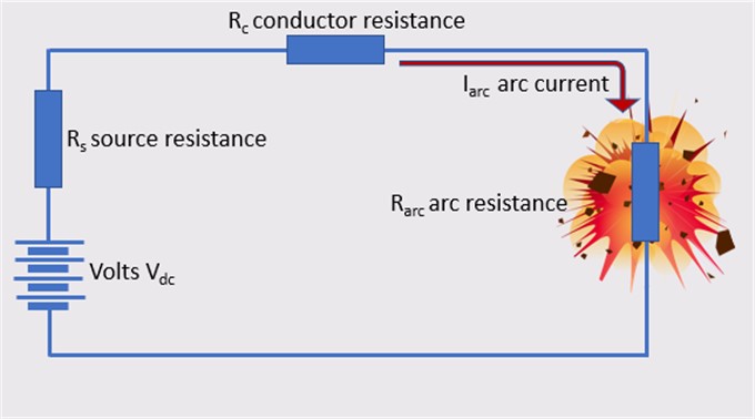
Figure 14.17 DC (Direct Current) Circuit
As can be seen we have two unknowns, Rarc and Idc arc. It is necessary to apply an estimate of arcing current of 50% of the prospective short circuit current in order to get an estimate of arcing resistance Rarc. This is the voltage divided by the sum of Rc and Rs which gives us the prospective short circuit current multiplied by 50% giving the estimate of arcing current. This estimate is entered into the above equation to give a first arc resistance. This is added to the actual values of Rc and Rs which reveals a total estimated impedance which is divided into the voltage once more to determine a new value of arcing current. This new arcing current is used in the above equation and once again a new value of arc resistance is determined. This is repeated and through a process of iteration steps, the calculated values of both arcing current and arc resistance will get closer to the previous values until there is no significant difference.
The next stage in the calculation process is to find the arc energy Earc using the formulae P = I2 x R x t watt/seconds using the calculated values for arcing current Idc arc and arc resistance Rarc. The value t is the disconnection time of the circuit which is found by consulting the upstream protective device time current curve.
If the arc is in open air, the incident is found as follows:
| Ei air = |
|
Where d is the distance measured from the arc source to the worker. This result is in cal/cm2
If the arc is enclosed, then factors are selected in accordance with the following table.
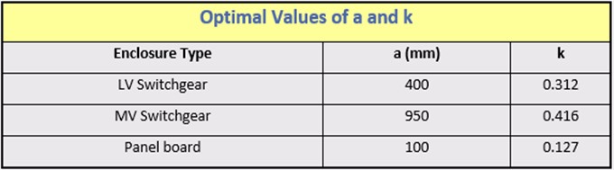
Table 14.18 Optimal Values for Enclosure Types
The enclosed (box) incident energy is found using the following equation:
| Ei box = |
|
This result is in cal/cm2
References
- Complete Guide to Arc Flash Hazard Calculation Studies by Jim Phillips P.E – Brainfiller Inc. 2010
- DC Arc Flash Calculations by Jim Phillips – Posted on Brainfiller.com, November 20, 2019
- Arc Flash Calculations for Exposures to DC Systems by D.R. Doan – IEEE Transactions on Industry Applications, Vol.46 No 5
- DC Arc Models and Incident Energy Calculations by R.F. Ammerman, T. Gammon, P.K. Sen and J.P. Nelson – IEEE Transactions on Industry Applications, Vol.46 No 6
- Electric Arcs in open Air by A.D.Stokes and W.T.Oppenlander – Journal of Physics D: Applied Physics 1991
- Simple Improved Equations for Arc Flash Analysis by R. Wilkins – IEEE Electrical Safety Forum, August 30, 2004.