LV Circuit Breaker Calculator Guide (Level 2)
What is it?
This incident energy calculator gives very quick results for circuits that are fed from low voltage air circuit breakers (ACB), moulded case circuit breakers (MCCB), and miniature circuit breakers (MCB) that are in common use within Europe. It is based upon IEEE 1584:2018 Guide for Performing Arc Flash Hazard Calculations. More information can be found in Chapter 4: Prediction and Chapter 14: Hazard and Severity Calculators.
Why would you use it?
Risk assessment is the bedrock of this guide in managing the arc flash hazard. Chapter 3: Risk Assessment and the 4P Guide explains that the first step is predicting the hazard severity and a calculation of the incident energy will allow you to determine the thermal effects of a possible arcing event. This calculator has several advantages as follows.
- The user will be able to check against a list of circuit breakers in common use in Europe.
- The user will require an estimate of the fault current at the equipment and does not require a copy of the time current curve providing the upstream device is listed on the dropdown menu or the upstream device meets with the criteria detailed below.
- This is a major advantage of the guide as it fits with the philosophy of simplicity.
- The method will help to establish real danger where settings are borderline.
Where would you use it?
The calculator is most useful where there is limited information about the system to be worked upon or in proximity to. The calculator has limitations; it cannot be applied to every situation, is suitable for systems having:
- Voltages in the range of 208V to 15,000V. Three-phase.
- Frequencies of 50 or 60 Hz.
-
Bolted fault current (Prospective Short Circuit Current) in the range of:
- 700A to 106,000A for voltages between 208 and 600 volts.
- 200A to 65,000A for voltages between 601 and 15,000 volts.
- Working Distances greater than or equal to 305mm.
- Grounding of all types and Ungrounded.
-
Gaps between conductors in the range of:
- 6.35mm to 76.2mm for voltages between 208 and 600 volts.
- 19.05mm to 254mm for voltages between 601 and 15,000 volts.
- Faults involving three phases only.
- AC (Alternating Current) Faults only.
How do you use it?
The following sets out how a competent electrical engineer can use the calculator to arrive at an incident energy level at a stated working distance as well as an arc flash boundary which is the distance at which the incident energy level equals 1.2 cal/cm2 (or the threshold of a second-degree burn).
The Circuit Breaker calculator tool follows the principle that a calculation is made to determine the minimum fault current to operate a circuit breaker instantaneously. It will allow for results from low voltage air circuit breakers (ACB), moulded case circuit breakers (MCCB) and miniature circuit breakers (MCB).
The following graph shows the Time Current Curve for a typical LV Circuit Breaker:
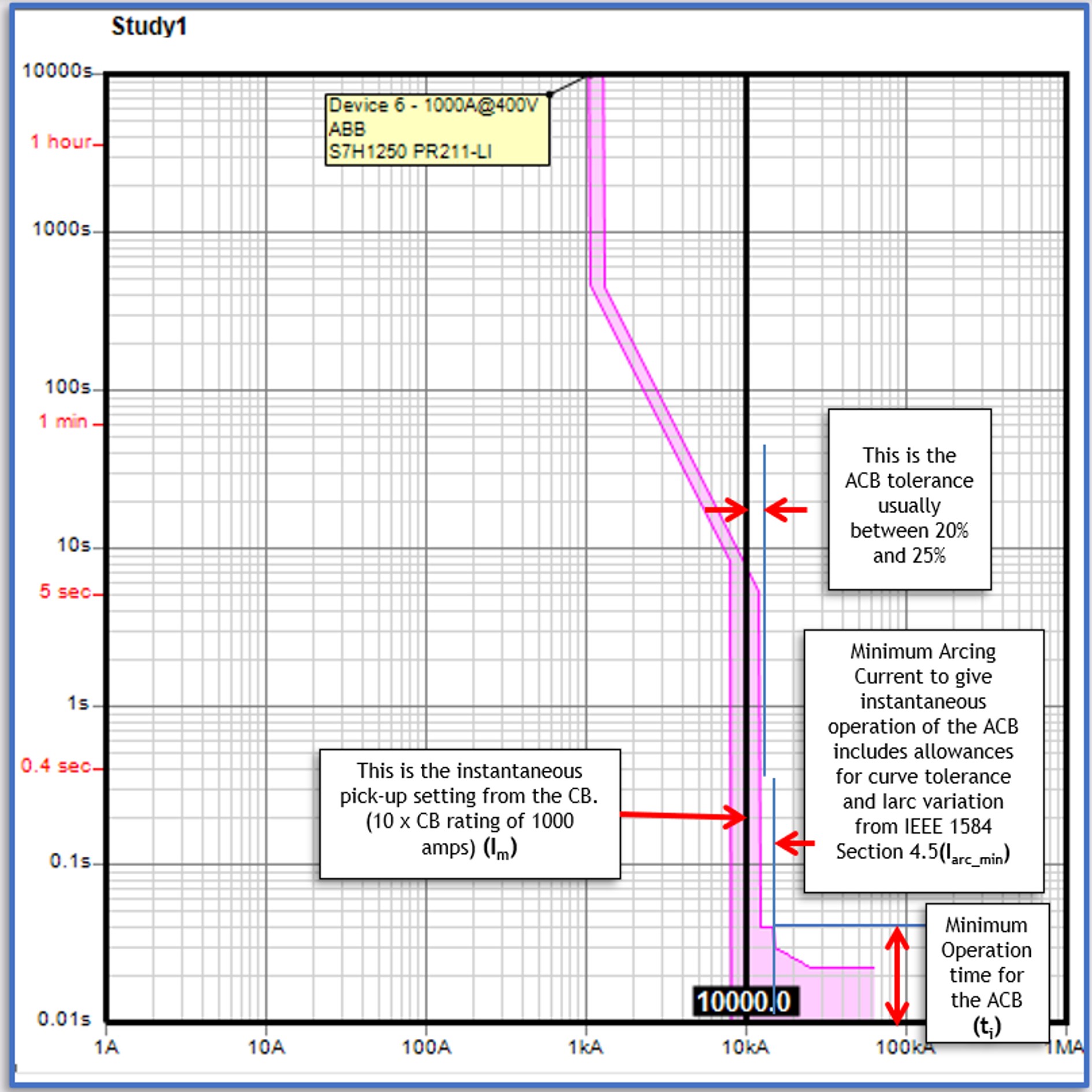
Figure 14.8 TCC Curve
As can be seen from the typical example given in Figure 14.8, the instantaneous pick-up setting from the circuit breaker is shown. In this particular case, this is 10 times the CB rating of 1000 amperes which we will call (Im). Time current curves from major manufacturers such as Siemens, Mitsubishi, Terasaki, Schneider, ABB, Eaton, Dorman Smith are mostly within a maximum tolerance of 25% but the individual circuit breakers are listed to state that they have been checked. Also shown is the minimum arcing current to give instantaneous operation of the CB and the listed circuit breakers all fall within a maximum instantaneous clearance time of 80ms. This figure includes allowances for curve tolerance and for the arcing current variation correction factor (Iarc_min) from IEEE 1584:2018 guide. Where a circuit breaker is not listed, the user can verify that the CB fulfils the clearance criteria of 25% tolerance and minimum instantaneous operating time of 80ms.
The calculator determines the arcing fault current from the data that the user has provided which will be the electrode configuration, conductor gap, voltage, instantaneous setting and prospective short circuit current. The calculator has a YES/NO dropdown menu to state that the instantaneous element is switched on. The incident energy and arc flash boundary will be displayed after the user has entered the working distance and be based on the minimum operation time for the circuit breaker (It) and arcing current (Iarc_min). The dropdown menu will be displayed which will list all the circuit breakers to which the calculator applies. Should the arcing current be below the current to give instantaneous operation of the ACB the incident energy will be calculated based upon a maximum time of two seconds*. The following diagram, Figure 14.9 shows a typical over current characteristic.
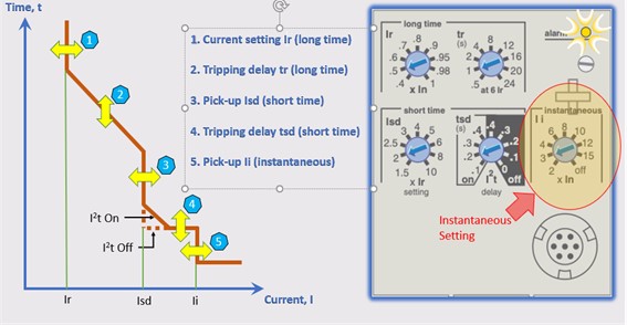
Figure 14.9 Typical Overcurrent Characteristics for Integral Trip Units
*NOTE: The IEEE 1584:2018 states “If the total protective device clearing time is longer than two seconds, consider how long a person is likely to remain in the location of the arc flash. It is likely that a person exposed to an arc flash will move away quickly if it is physically possible, and two seconds usually is a reasonable assumption for the arc duration to determine the incident energy.”
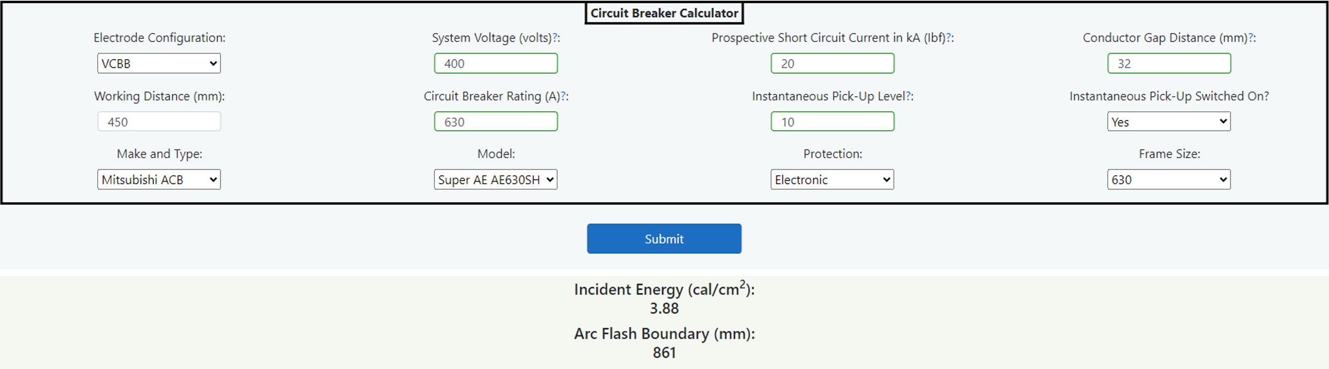
Figure 14.10 Circuit Breaker Calculator
The following is a description of the input/output fields:
Electrode Configuration
There are five different electrode configurations, and this field is a dropdown list giving choices as follows:- VCB: Vertical conductors/electrodes inside a metal box/enclosure.
- VCBB: Vertical conductors/electrodes terminated in an insulating barrier inside a metal box/enclosure.
- HCB: Horizontal conductors/electrodes inside a metal box/enclosure.
- VOA: Vertical conductors/electrodes in open air.
- HOA: Horizontal conductors/electrodes in open air.
Chapter 8: Data Collection describes which electrode configuration to use as the choice will determine not only the arcing current but also the incident energy and arc flash boundaries.
System Voltage (volts)
The three-phase line-to-line voltage in volts.
Prospective Short Circuit Current
This is the user’s estimate of prospective short circuit current in kA trying to take into account system variations.The user is advised to enter both upper and lower limits of prospective short circuit current to determine which produces the worst case incident energy. A lower short circuit current can result in a higher value of incident energy.
Conductor Gap (mm)
Enter the gap between conductors at the equipment. This may need some engineering judgement as described in Chapter 8: Data Collection.
Working Distance (mm)
This is the distance between the potential arc source (not just the front of the panel) and the face and chest of the worker.
Circuit Breaker Rating (amperes)
This is the overcurrent rating of the circuit breaker or long-time current setting as shown in Figure 14.9 earlier, (not the frame size or rating).
Instantaneous Pick-Up Level
This is the instantaneous setting which is usually between 2 and 15 times the overcurrent circuit breaker rating for integral electronic trip units. This may be a fixed value on older thermal magnetic trips and miniature circuit breakers.
Instantaneous Pick-Up Switched On?
Verify that the instantaneous section or setting is switched to on. The calculator has a YES/NO dropdown menu to state that the instantaneous element is switched on by selecting YES. Select NO if the instantaneous setting is switched off.
Make and Type
Pick from a dropdown list of circuit breaker make and types. This is the first check to see if the circuit breaker is listed in a library of circuit breakers in use in Europe. For the circuit breakers to be listed, they will pass the criteria given later under circuit breaker listings. You can also select “(Valid) Make/Type Not Listed” in which case the circuit breaker meets the criteria but is not listed or “(Invalid) Make/Type Not Listed” and in this case the circuit breaker will always default to two seconds disconnection time.
Model
Pick from a dropdown list of circuit breaker models. If either the "(Valid) Model Not Listed" or "(Invalid) Model Not Listed" option is selected, the "Protection" box will not appear.
Protection
Pick from a dropdown list of circuit breaker integral protection unit types if fitted. If either the "(Valid) Protection Not Listed" or "(Invalid) Protection Not Listed" option is selected, the "Frame Size" box will not appear.
Frame Size
Pick from a dropdown list of circuit breaker frame sizes if given.
Incident Energy (cal/cm2)
The calculator will produce an incident energy level based upon either, instantaneous operation of the circuit breaker or a two second maximum disconnection time.
Arc Flash Boundary (mm)
The arc flash boundary will also be stated based upon either, instantaneous operation of the circuit breaker or a two second maximum disconnection time.Operating Logic
The calculator flowchart, Figure 14.11, shows the input sequence and the operating logic.
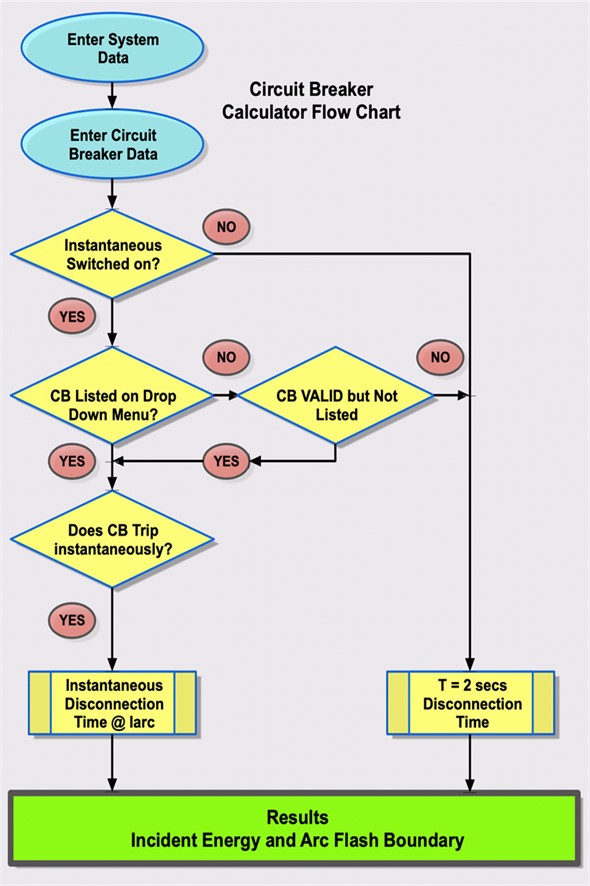
Figure 14.11 Circuit Breaker Calculator Flowchart
To use the calculator, first examine the upstream circuit breaker settings and determine the prospective short circuit current at the equipment to worked on or nearby. Verify that the circuit breaker is listed or that it complies with the tolerance values given in the dropdown field “Circuit Breaker”.
Enter the working distance (mm) which is the distance from an arcing source to the torso and/or head.
Determine the electrode configuration and conductor gap distance (mm), more information on electrode configuration is given in Chapter 8: Data Collection.
Enter the circuit breaker rating in amperes and the instantaneous pick-up level which has to be given as a multiplier of the rating. Verify that the instantaneous section or setting is switched to on and select YES from the dropdown menu. Select NO if the instantaneous setting is switched off.
A typical circuit breaker integral trip unit is shown in Figure 14.10. From the information given the calculator will produce an incident energy level and arc flash boundary based upon either, instantaneous operation of the circuit breaker or a two second maximum disconnection time.
Note: you must ensure that the short circuit rating and maintenance of the circuit breaker is correct and fit for purpose.
Operating Logic
The circuit breaker listing library contains over 8000 common circuit breakers in use in Europe. In order for the circuit breakers to be listed, they will pass the following criteria:
- The instantaneous element will be adjustable.
- The clearance curve tolerance will be no greater than 25% as explained previously.
- The minimum operation time for the circuit breaker will be no more than 0.08 seconds when operating in the instantaneous zone.
If the circuit breaker is not listed, then you can check that the parameters fit the above criteria and click the checked box. If there is no adjustable setting for the instantaneous setting, then check the manufacturer’s data.
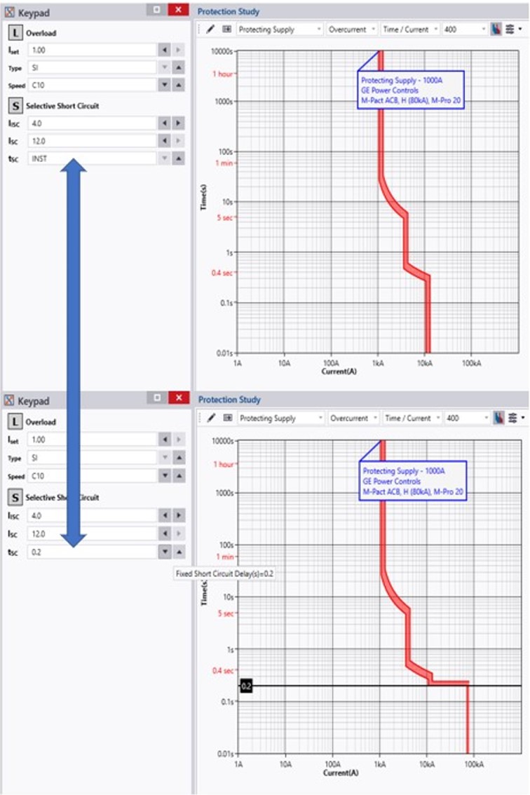
Figure 14.12 Example of the Time Delay Setting
The other thing to look out for is some circuit breakers provide a selective short circuit function with a time delay setting as in this example given in Figure 14.12. Make sure that the time delay is disabled and, in this case, tsc should be set to INST. As can be seen in this example, the selective short circuit setting can be set to instantaneous in which case there will be no intentional delay or, alternatively, a delay can be introduced.