Prospective Short Circuit Current Calculator Guide
What is it?
The prospective short circuit current calculator tool is useful to provide an estimate of the prospective short circuit current at the equipment where incident energy hazard evaluation is to be carried out.
Why would you use it?
By using the calculator, the prospective short circuit current can be determined which can then be used in the Incident energy calculator or to use the other tools that are available with this guide.
Where would you use it?
The calculator is based upon the impedance method which will provide an RMS symmetrical short circuit current which can be inputted directly into the IEEE 1584 Incident Energy Calculator. There is also a separate output of maximum and minimum fault currents in accordance with IEC 60909 Short-circuit currents in three-phase AC systems. This will be required for the DGUV-I-203-5188 E German Calculator if required. The limitations are:
- Three-phase short circuits up to a maximum secondary voltage of 600 volts.
- Symmetrical three-phase fault current only.
- Single radial circuits only.
- Main’s contributions only. Motor contribution can be included when using the IEEE 1584 Incident Energy Calculator.
- The cable resistance and reactance values are generic, users must satisfy themselves that these are a reasonable estimate.
How do you use it?
A screen shot of the calculator is shown in Figure 14.23 below.
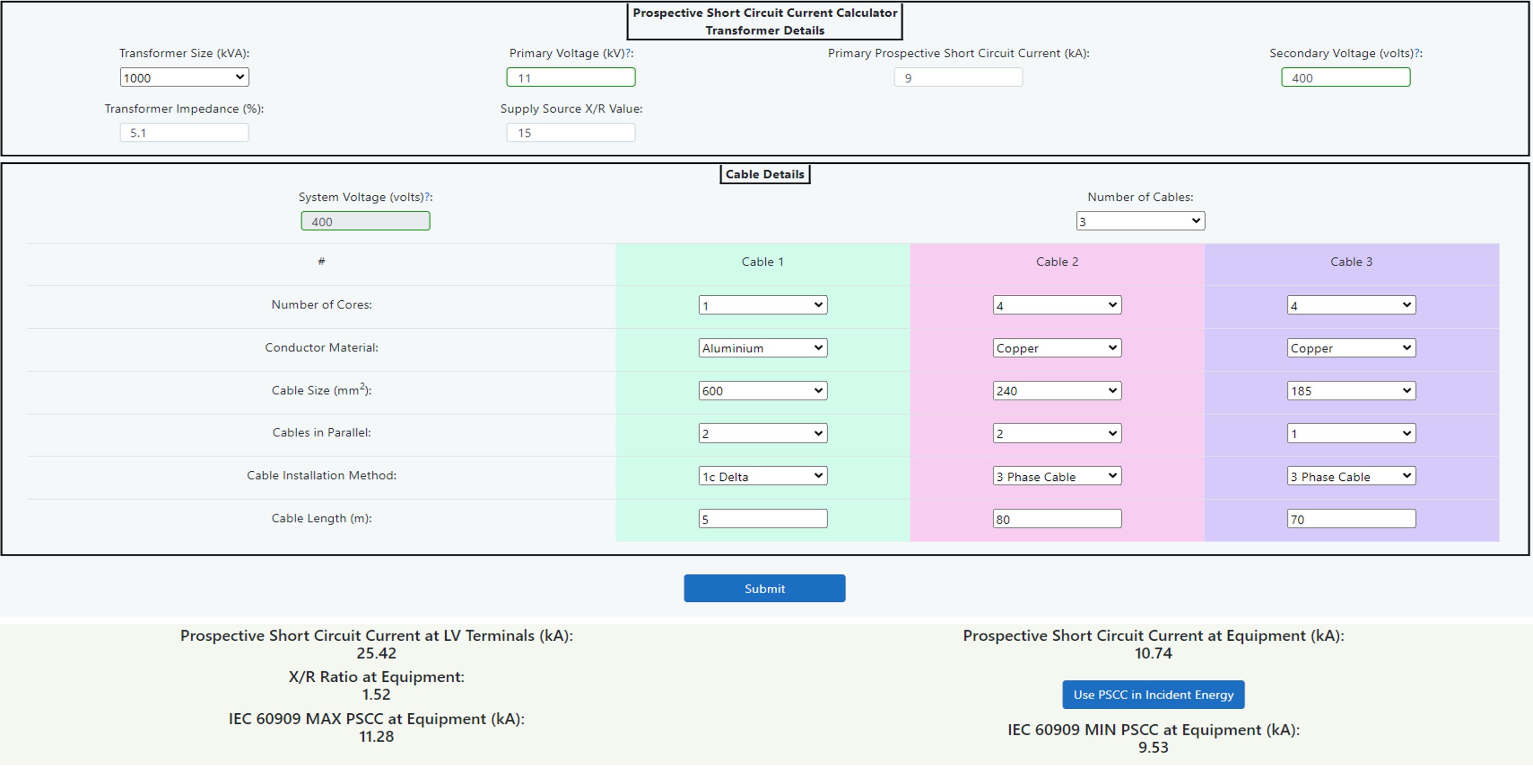
Figure 14.23 Prospective Short Circuit Current Calculator
The following diagram Figure 14.24 shows a single line representation of the components of the Prospective Short Circuit Current Calculator. In this case the equipment to be worked upon is represented by switchboard SB3 but this could alternatively be SB1 or SB2 simply by omitting the cable 3 or cables 2 and 3 respectively. The calculator should be used when equipment being studied has an upstream transformer device as the supply source or as an alternative, the transformer may be omitted to use the cable calculators only.
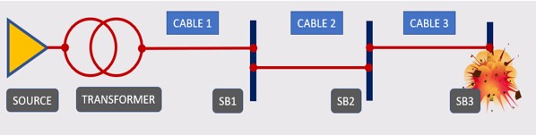
Figure 14.24 Single Line Diagram
Transformer
The transformer short circuit section can be used to determine prospective short circuit current and X/R ratio at the low voltage terminals of a transformer. The generic transformer X/R ratios are taken from several sources of information including different manufacturers and also IEEE 242 which suggests typical levels. The author has taken these values to create a table of reasonable averages for distribution type power transformers based upon voltages up to 20kV primary and up to 600 volts secondary. Transformers will all possess different specifications due to the nature of their manufacturing process, so a higher degree of accuracy is possible by obtaining the original transformer specification. The calculator is, however, much more accurate than taking manufacturer’s estimated LV (Low Voltage) fault data based upon infinite HV (High Voltage) impedance and average % impedance values.
To use this calculator:
- Inspect the transformer to be assessed taking note of kVA size, primary voltage, % impedance and secondary voltage. See Chapter 8: Data Collection for further guidance.
- Enter this information into the calculator by selecting/inputting the relevant data into the data entry fields.
- Contact the local utility supplier to determine the actual prospective short circuit current of the supply. It is always good practice to obtain the minimum fault level also as this could lead to a potentially longer disconnection time in the case of an arc flash.
As indicated in step 1 above the transformer impedance can be obtained from the transformer nameplate. Failing that, the following table 14.26 shows some standard impedance levels that can be used with a caution to apply some sensitivity validation (or what if analysis) to any incident energy levels obtained as a result.
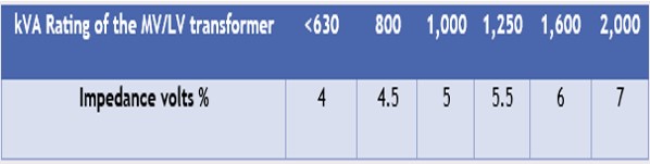
Table 14.26 Standardised short circuit voltage for public distribution transformers - Source: Schneider Electric
The calculator also uses the following table, Table 14.27 of average X/R ratios for transformer kVA sizes as described below.
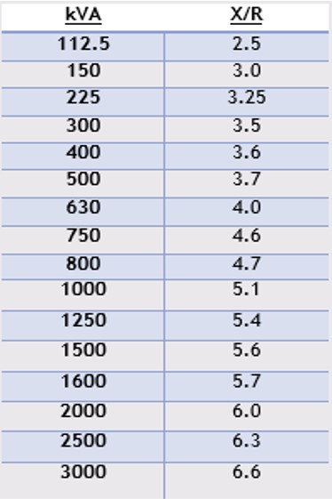
Table 14.27 X/R Ratios
The calculator will then produce results for the prospective short circuit current and the X/R ratio at the Low Voltage terminals. These values can then be used in the fault current level calculator to make allowances for cabling between the transformer and the equipment.
Please note that this tool is valid only for transformers up to 20kV on the primary side and up to 600V on the secondary side only. For transformers above either of these values, contact the manufacturer for X/R values. Note also that this calculator assumes a typical high voltage source X/R value of 15. Although this is a fair assumption for most situations, this still would require consideration to ensure that the calculator’s assumptions are correct for the specific transformer being assessed.
This calculator should be used when equipment being studied has an upstream transformer or low voltage mains from a utility company as the supply source. By using the calculator, the prospective short circuit current can be determined which can then be used in the incident energy calculator.
Cables
The calculator tool shown is useful to provide an estimate of the prospective short circuit current at the equipment based upon Schneider Electric Cahier technique no. 158 “Calculation of short-circuit currents” by Metz-Noblat, Dumas and Poulain. This is a very useful technique to provide conductor resistance and reactance values based upon material resistivity calculations and average reactance values. When calculated to this method, the results are very similar to the generic cable resistance for non-flexible cables (stranding class 2) found in BS EN 60228 standard on conductors of insulated cables. The tool requires information about the system voltage, source prospective short circuit current, X/R ratio and details about the cables between the supply and the equipment itself. The prospective fault current is based upon the cable temperature at 20°C.
The prospective short circuit current at the equipment can be found by:
- Determine the system voltage, source prospective short circuit current and the X/R ratio and enter the data into the calculator. This is not required if the transformer calculator has been used above.
- Assess the cabling between the source and the equipment noting conductor material, number of cables in parallel, number of cores for each cable, cable size and length. Enter the data into cable 1 by selecting from the dropdown lists provided. See Chapter 8: Data Collection for further guidance.
- If there are multiple cable types in series from the source to the equipment, take note of each cable’s parameters as in step 2 and enter the extra cable data into the optional cables 2 and 3 by selecting the relevant dropdown list options provided.
After the above steps have been followed, the tool will generate an estimated prospective short circuit current at the equipment which can be used in the incident energy calculator or other estimation modules provided.
The cable resistance and reactance values are generic and whilst this will allow for a reasonable estimate, cable manufacturing processes and materials will inevitably lead to variances. The generic values are given below in Figure 14.28 and users are advised to satisfy themselves of their accuracy.
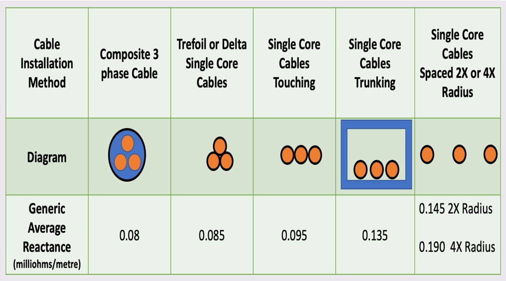
Figure 14.28 Average Reactance Values - Source: Schneider Electric
As can be seen, the reactance values can vary widely with different installation methods and any electrical engineer who is carrying out retrospective system studies needs to be aware of this fact.
The resistance values are based up ρ0 = resistivity of conductors at 20°C = 0.01851 Ω mm2/m for copper and 0.02941 Ω mm2/m for aluminium. For loaded conductors in order to obtain a minimum short circuit current in accordance with IEC 60909, see later paragraph, a multiplication factor of 1.25 has been used. This factor will return a value which is in line with a conductor operating temperature maximum of 90°C which should be conservative for power systems.
Please note that this tool is only valid for system voltages between 208V to 600V (three-phase AC) and a source prospective short circuit current of between 500A to 106,000A.
IEC 60909 Maximum and Minimum Prospective Short Circuit Current
A further feature of the calculator is that you can obtain a maximum and minimum prospective short circuit current in accordance with IEC 60909: Short circuit currents in three-phase AC systems. To use the DGUV Box Test Algorithm it will be necessary to have both maximum and minimum figures and the voltage correction factors given below are as stated in DGUV-I-203-5188 E. The IEEE 1584 guide calculates an arc variation factor which will reduce the arcing current in order to take into account fluctuations in fault currents.
This is calculated as follows:
- The maximum short circuit current is found by applying a voltage factor c to the estimated prospective short circuit current above which was based upon conductor temperature of 20°C. The voltage factor is based upon a 6% tolerance giving a factor of cmax = 1.05.
- The minimum short circuit current is found by calculating the estimated prospective short circuit current based upon fully loaded conductors which are operating at design temperature maximum of 90°C and the applying a voltage factor cmin. The voltage factor is based upon a 6% tolerance giving a factor of cmin = 0.95.
To summarise, the following is a list of data entry and output fields from the calculator.
TRANSFORMER DETAILS SECTION
Transformer Size (kVA)
Select the transformer size from a dropdown list of distribution transformers from 112.5 kVA up to 3000 kVA. If there is no transformer and the source is at low voltage from a utility company, select “NA” and go directly to the cable details section.
Primary Voltage (kV)
Enter the primary voltage to the transformer up to a maximum of 20 kA.
Prospective Short Circuit Current (kA)
Enter a figure for the prospective short circuit current at the primary of the transformer.
Secondary Voltage (volts)
Enter the secondary three-phase line-to-line voltage at the transformer low voltage terminals between 208 and 600 volts. This figure will also be used for the Cable Voltage when the transformer is used.
Transformer Impedance (%)
Enter the % transformer impedance figure which can be found on the transformer nameplate.
Supply Source X/R Value
The calculator assumes a typical high voltage source X/R value of 15 but a specific X/R ratio can be entered.CABLE DETAILS SECTION
System Voltage (volts) (No transformer)
If there is no transformer used, enter the low voltage three-phase line-to-line system voltage in volts. This field is only editable when the transformer size is set to "NA".
Source Prospective Short Circuit Current (kA) (No transformer)
If there is no transformer used, enter a figure for the prospective short circuit current for the low voltage source. This field is only available when the transformer size is set to "NA".
Source X/R Value (No transformer)
If there is no transformer used, enter a source X/R value, otherwise a default value of X/R = 1, or whatever your specific preset configuration is will be used. This field is only available when the transformer size is set to "NA".
Number of Cables
Enter the number of cables that will be used between the supply source and the equipment up to a maximum of three. A data entry block will be displayed for each cable. Cable one will always be the nearest to the supply source as in the single line schematic shown earlier.
Number of Cores
Enter the number of cores for each cable used.
Conductor Material
Select conductor material as aluminium or copper from the dropdown field.
Cable Size (mm2)
Choose a cross sectional area of each conductor from the dropdown list from between 16 mm2 up to 1000 mm2.
Cables in Parallel
Choose the number of cables installed in parallel from the dropdown list.
Cable Installation Method
Choose the cable installation method from the dropdown list.
Cable Length (m)
Enter the length of the cable in metres.OUTPUTS
Prospective Short Circuit Current at LV Terminals (kA)
This is the symmetrical prospective short circuit current at the low voltage source, transformer low voltage terminals or low voltage utility mains.
X/R ratio at Equipment
This is the X/R ratio at the Equipment.
Prospective Short Circuit Current at Equipment (kA)
This is the symmetrical prospective short circuit current at the equipment after calculating impedances of the supply source and all cables. This figure can be used to input directly into the IEEE 1584 incident energy calculator by selecting the “Use PSCC in Incident Energy” option button.
IEC 60909 MAX PSCC at Equipment (kA)
As described in this chapter an output is given for the symmetrical maximum prospective short circuit current as calculated using IEC 60909 correction factors.