Incident Energy HRC Fuse Chart Guide (Level 2)
What is it?
The fuse charts give very quick results for circuits that are fed from low voltage fuses that are in common use in Europe. They are based upon IEEE 1584:2018 Guide for Performing Arc Flash Hazard Calculations. More information can be found in Chapter 4: Prediction and Chapter 14: Hazard and Severity Calculators.
Why would you use it?
The fuse charts give a very quick and simple way of determining incident energy as part of dynamic risk assessments as well as exposing danger.
Where would you use it?
The fuse charts are useful where there is limited information about the system to be worked upon or in proximity to. The fuse charts give a very quick and simple way of determining incident energy as part of dynamic risk assessments as well as exposing danger. They are based upon the two most popular fuses in Europe which are the BS88 and DIN NH models. Both are extremely efficient in clearing high energy faults very quickly and safely where there is sufficient available fault level. The range of the fuse charts are as follows:
- The voltage used is 400 volts which is the harmonised voltage in Europe.
- Fuse sizes are from 160 amperes up to 800 amperes.
- The charts are valid for IEEE 1584:2018 Guide for Performing Arc Flash Calculations.
- Electrode configurations covered are VCB. Other configurations will need to be determined using the IEEE 1584 calculator tool.
- There is a two second maximum reaction time* applied which means that sufficient space is available to pull back from an arcing event. So, the charts are not valid where the worker is confined by the constraints of the working area.
- Frequencies of 50 or 60 Hz.
- Bolted fault current (Prospective Short Circuit Current) in the range of: 0.7kA to 80kA.
- Working Distances: 450 mm.
- Gaps between conductors: 32 mm
- Grounding of all types and Ungrounded.
- Equipment enclosure sizes 508 x 508 x 508 mm.
- Faults involving three phases only.
- AC (Alternating Current) Faults only.
*NOTE: The IEEE 1584:2018 Guide states “If the total protective device clearing time is longer than two seconds, consider how long a person is likely to remain in the location of the arc flash. It is likely that a person exposed to an arc flash will move away quickly if it is physically possible, and two seconds usually is a reasonable assumption for the arc duration to determine the incident energy.”
How do you use it?
The following sets out how a competent electrical engineer can use the calculator to arrive at an incident energy level at a stated working distance as well as an arc flash boundary which is the distance at which the incident energy level equals 1.2 cal/cm2 (or the threshold of a second-degree burn).
The principle behind the charts is that the area which is outside the current limiting zone of the fuses, is expressed as the danger zone. The following chart, Figure 14.13, shows a plot of incident energy against prospective short circuit current at the equipment in question. This is derived from a calculation of arcing current and the corresponding determination of disconnection time provides the basis for incident energy levels to be established over the fault handling capability range of the fuse. This is based upon a working distance of 450mm between the source of the arc and the worker.
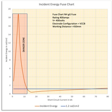
Figure 14.13 IE (Incident Energy) Fuse Chart
From the above, we can highlight the key parameters of the danger zone and the short circuit current at which the corresponding arcing current that will cause the fuse to operate the current limiting zone. In this case, the 400-ampere fuse will protect in the current limiting area for prospective short circuit current values greater than 12 kA. Below that figure, operation will be slower meaning that the incident energy level will build up to 19 cal/cm2 at which point the maximum disconnection time of two seconds will kick in. For simplicity, the charts will show the zones of protection as follows in figure 14.14. In this case a BS88 315 ampere fuse link is used.
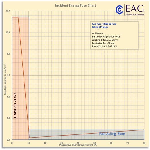
Figure 14.14 Simplified IE (Incident Energy) Fuse Chart - For Illustration Purposes ONLY
All that the user will require is an estimate of the prospective short circuit current at the equipment and to check that the chart will fall in line with the range limitations given previously. Use of the charts will give an instant prompt of whether to STOP or to carry out further action to ensure the safety of workers.