Low Voltage Overhead Lines. Three phase and neutral LV open overhead lines are typically aluminium conductors spaced at 300mm to the Electricity Supply Industry Standard. They are usually spaced at 225mm for 3 phase lines and 150mm for single phase lines. Even at the single phase spacing of 150mm, this is at the limit of validity for the IEEE 1584 calculations. The initiation and viability of a low voltage electric arc at such spacing would be difficult to achieve but where cable tap offs are introduced this could be more likely. A spacing of 32mm was therefore, used to simulate a fault in open air.
The majority of LV overhead lines were fed at fuse ratings of BS 88 - 315 amperes or less but in cases where a larger fuse was used, a decision was taken to adopt the maximum incident energy levels reported under LV underground activities.
The vast majority of overhead line work is undertaken from mobile elevated work platforms but there are occasions when energised work is carried out by climbing.
As can be seen from the images in Figure 11.1, the distances to the worker can be greatly reduced and also the linesman can only retract as far as the limits of his belt. The linesman is shown retracted from a possible arcing incident. The working distance for the following are: Lower torso, 450mm; Chest, 600mm; Hands, 450mm; Face, over 1000mm. This meant that reliance cannot be made on a maximum disconnection time when climbing.
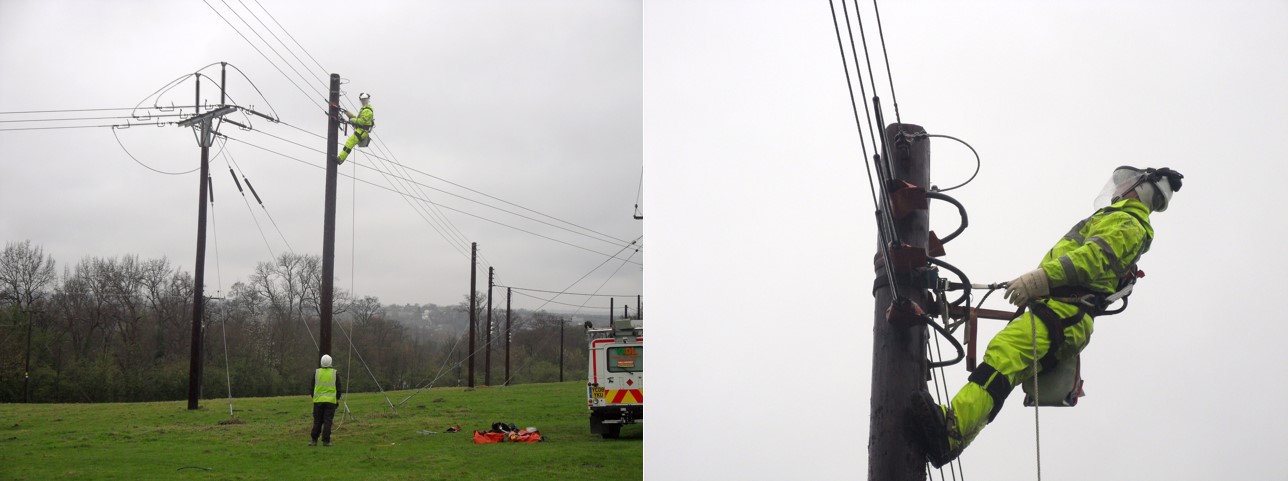
Figure 11.1 Live Line Work
The solution may be to carry out individual risk assessments and determine the fault level at the point of work. Charts were developed to display fault level against incident energy for various BS 88 fuse ratings.
Parallel configurations between substations. Link box operations are often perceived to have high risk because a parallel arrangement is being made manually by the operator. Engineers often report arcing usually because of a “bad parallel” between transformers rather than a short circuit at the link box but there is a possibility that arcing can occur due to fault conditions. It was possible to simulate conditions where the incident energy could be in the region of 24 cal/cm2 with 400A fuses and 28 cal/cm2 with 500A fuses at the sources feeding from both ends for a working distance of 450mm. In some cases, the engineer may have to stand on top of the link box to carry out operational tasks such as testing or linking. A recommendation was that no live working be permitted whilst a parallel arrangement exists.
Temporary Generator Connections–Fault Contributions. When generators are paralleled onto LV boards this will clearly have an effect on the fault level and incident energy levels on the network. From the data sheets that were created, it was observed that the incident energy could rise from a norm of 20-30 cal/cm2 to levels over 100 cal/cm2 in some cases. The protective device at the generator connection and the HV circuit breaker will need to clear the fault independently. Again, a recommendation was that no live working be permitted whilst a parallel arrangement exists.
Fault contributions from large LV industrial induction motors. A 200 kW motor was connected into the model at an industrial service unit and fault contribution was seen to have a considerable effect on incident energy. A 50% increase was observed at the highest fault level. It is unlikely that a motor of that size would be connected directly onto a main feeding a district and that it would normally be fed independently. It can be assumed however, that where such large motors are connected at low voltage then the LV figures given in this report can be raised by a factor of 50%. This information does have significance for system design engineers when dealing with new connection requests.
Incident Energy Levels at Hands and Forearms. For most live working activities, the distance to the hands and forearms is likely to be less than those given to head and torso and therefore, the incident energy is likely to be much greater. This needs to be taken into account when choosing the type of hand protection that will be required to combat arc flash although incident energy tests have been performed on both insulating gloves and leather protectors. It is generally accepted that this combination of hand protection will offer some protection although injury to hands cannot be ruled out. See Chapter 7: Protection for further up to date information.
High Voltage Secondary Substation Operations. A separate “Task and Working Distance Report” for high voltage secondary operations was produced which shows the most common switchgear. Although fully arc protected equipment has been purchased in the previous 15 years, like most Utilities there is a good deal of non-arc protected equipment in use and much of the older switchgear is also oil filled. The IEEE 1584 calculations cannot predict the ballistic effects of disruptive failure inside non arc protected switchgear, nor can it predict the effects of oil ignition. The incident energy levels were reported for those activities where there is interaction with feeder spouts either through racking in, locking off or testing. The data created used a generic arc gap of 153mm and a working distance of 900 mm. Scenarios were created using a 185mm aluminium conductor backed up by standard inverse protection set at 150% and 0.7 seconds at the given maximum fault current. This was all repeated for six different fault levels and four different feeder lengths.
High Voltage (11kV Feeder) cable strikes. A similar exercise to the above was conducted to simulate cable strikes. Incident energy level tables were produced to show the expected levels at damaged 11 kV cables at the same range of fault levels and feeder lengths. There were two data sets, the first shows the incident energy at a working distance of 900mm and the second for 300mm bearing in mind that the employee or third party may be standing over the fault.
Comments on Future Strategy. The data that was produced from the report was primarily for the selection and design of PPE but was also a valuable resource to influence future risk assessments. There were situations that highlighted dangerously high levels of incident energy and this should inform the judgments to allow work on or in the vicinity of energised equipment to be allowed to proceed. The importance of working space and stance when undertaking live proximity work was another learning point. For instance, a fairly modest increase in joint hole size can make a significant difference to incident energy exposure. A further learning point was that that the highest incident energy level on a low voltage main was not at a point nearest to the originating substation, but some 450 metres away. This phenomenon is something that I have referred to as the “fault level paradox” over many years and is talked about in Chapter 4: Prediction. For high voltage cables, the opposite was true in the studies and incident energy levels tend to be higher when closer to the supply source.
Clearly, the use of PPE should always be as a last resort and other risk reduction and mitigation techniques should always be explored not forgetting that the first duty should be to remove the hazard entirely. Arcing faults can be predicted and should be part of system design to engineer the problem out. At low voltage for instance, engineers know at which point voltage drop or earth loop impedance may start to become a problem and very often it is system impedance which will affect the severity of an electrical arc.