Further Important Information
All fields that have specific validation are accompanied with an instructional tooltip, denoted by a “?”. If the instruction is followed correctly, in most cases the field will appear green, if it is erroneous, it will appear red.
Results.
The results are displayed in two formats: Format 1 where the arcing current Iarc and associated
disconnection time returns the highest incident energy and arc flash boundary. Format 2 displays the
incident energy and arc flash boundary for the arcing current Iarc_min where this is higher than format 1.
This is usually because of longer disconnection times due to the lower arcing current.
14.2 LV Circuit Breaker Calculator (LEVEL 2)
The Circuit Breaker calculator tool follows the principle that a calculation is made to determine the minimum fault current to operate a circuit breaker instantaneously. It will allow for results from low voltage air circuit breakers (ACB), moulded case circuit breakers (MCCB) and miniature circuit breakers (MCB).
The calculator has several advantages as follows.
- The user will be able to check against a list of circuit breakers in common use in Europe.
- The user will require an estimate of the fault current at the equipment and does not require a copy of the time current curve providing the upstream device is listed on the drop-down menu or the upstream device meets with the criteria detailed below.
- This is a major advantage of the guide as it fits with the philosophy of simplicity.
- The method will help to establish real danger where settings are borderline.
The following graph Figure 14.8, shows the Time Current Characteristic for a typical LV Circuit Breaker:
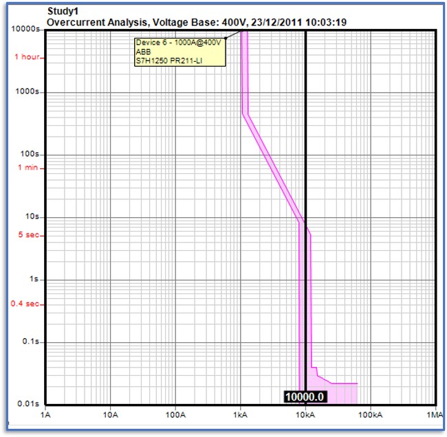
Figure 14.8 LV Circuit breaker time current characteristic
As can be seen from the typical example given in Figure 14.8, the instantaneous pick-up setting from the circuit breaker is shown. In this particular case, this is 10 times the CB rating of 1000 amperes which we will call (Im). Time current curves from major manufacturers such as Siemens, Mitsubishi, Terasaki, Schneider, ABB, Eaton, Dorman Smith are mostly within a maximum tolerance of 25% but the individual circuit breakers are listed to state that they have been checked. Also shown is the minimum arcing current to give instantaneous operation of the CB and the listed circuit breakers all fall within a maximum instantaneous clearance time of 80ms. This figure includes allowances for curve tolerance and for the arcing current variation correction factor (Iarc_min) from IEEE 1584 2018 guide. Where a circuit breaker is not listed, the user can verify that the CB fulfils the clearance criteria of 25% tolerance and minimum instantaneous operating time of 80ms.
The calculator determines the arcing fault current from the data that the user has provided which will be the electrode configuration, conductor gap, voltage, instantaneous setting and prospective short circuit current. The calculator has a YES/NO drop-down menu to state that the instantaneous element is switched on. The incident energy and arc flash boundary will be displayed after the user has entered the working distance and be based on the minimum operation time for the circuit breaker (It) and arcing current (Iarc_min). The drop-down menu will be displayed which will list all the circuit breakers to which the calculator applies. Should the arcing current be below the current to give instantaneous operation of the ACB the incident energy will be calculated based upon a maximum time of two seconds*. The following diagram, Figure 14.9 shows a typical over current characteristic.
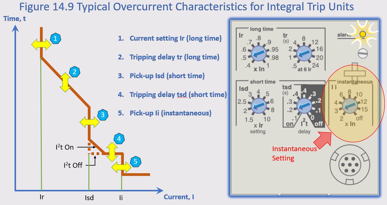
Figure 14.9
*NOTE: IEEE1584 Guide 2018 says “If the total protective device clearing time is longer than two seconds, consider how long a person is likely to remain in the location of the arc flash. It is likely that a person exposed to an arc flash will move away quickly if it is physically possible, and two seconds usually is a reasonable assumption for the arc duration to determine the incident energy.”