15.8 Providing knowledge to workers.
I believe that information and training can make a step change in safety practices to reduce harm from arcing faults. Electrical workers are often the ones who suffer from arcing incidents and yet they know surprisingly little about the phenomena. For instance, the mistaken belief that low fault level means less harm can lead to a false sense of security. There may be others out there who remember the GEC videos from over 50 years ago showing switchgear explosions and how BS 88 fuses reduced the damage to zero by disconnecting high fault currents very rapidly. The video shows the catastrophic damage from impressive explosions if the fuse links were replaced with solid copper links at a prospective short circuit current level of 38,000 and 60,000 amperes. The fuse links disconnect the fault current in less than one half cycle. The reason for this is that the fuse operates in its current limiting zone. The diagram in Figure 15.1 shows that for arcing faults, very little incident energy will be generated IF there is enough prospective short circuit current available to rupture the fuse quickly. But, as can be seen, fault levels below 12kA will result in high incident energy which can cause serious damage and harm to workers nearby.
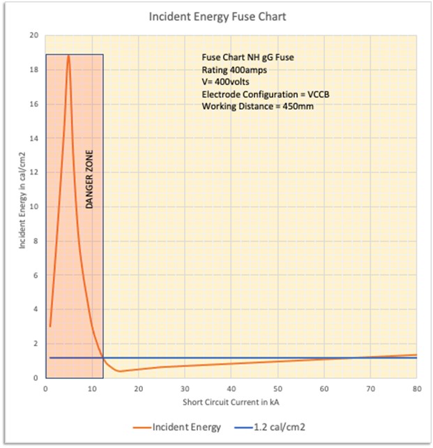
Figure 15.1
As is the case with shock protection, circuit impedance can be the enemy to safe automatic disconnection of supply. The electrician or engineer knows the voltage inside that control panel or switchgear so why should he or she not know the arc flash hazard level. By the way, the GEC video is still available on YouTube. Just enter “BS88 HRC fuse tests” into your search engine.
15.9 An essential tool for the designer.
The designer does not necessarily need to know the actual incident energy or arc flash boundary but definitely needs to have confidence that his or her electrical protection arrangements will clear dangerous faults. This includes arcing faults! For traditional overcurrent protection, the information that will be required to fulfil this duty will be the amount of current that will flow in a fault. With that information, it can be assured that the protective device will operate in the instantaneous zone of the time current characteristic wherever that is possible. A few amperes can be the difference between safe clearance or destructive energy let through.
Predicting the severity of the arc hazard, including the arcing current, has been made more reliable in recent years through the publication of IEEE 1584 Guide for Performing Arc-Flash Hazard Calculations 2018. It is an auditable standard and widely accepted in the electrical engineering community. Two hundred technical experts were involved in the development of the guide over many years and was based on over 1860 tests performed at different voltage levels in high current laboratories. To quote from the scope of the Guide: “The purpose of the guide is to enable qualified person(s) to analyse power systems for the purpose of calculating the incident energy to which employees could be exposed during operations and maintenance work”. It gives no recommendations for PPE. IEEE 1584 is therefore the flagship standard for determining the incident energy (thermal hazard) from an arc at three phase voltages in the range 208 volts to 15,000 volts AC.
(For the UK. Because designers now have the tools to predict arcing currents nowadays, I believe that there is less of a defence under EAWR Regulation 11 “Means for protecting from excess of current” as described in in the commentary in HSR 25.)
15.10 Improves electrical safety management.
My strongly held belief is that by carrying out arc flash calculations, that it will inevitably force a fresh view of many of the components of a good electrical safety management program. In order to carry out the calculations effectively you will look at the equipment to be worked on or near which usually means control panels and switchgear in industrial settings. Purely on the basis of discovering system parameters you will need to know what the fault levels are and what is the strength and capability of the equipment and upstream protective devices. The big question that will crop up is, are you competent that the protective systems will operate in accordance with design parameters? The likelihood of the hazard causing harm will be influenced by the conditions of the electrical system or equipment and also the task to be performed. Set this against the guidance of Chapters 5 and 6, Prevention and Process and it will become apparent that there is often a need to take immediate action to prevent unacceptable risk. Calculations will force you to look closely at equipment like process control panels which often highlights neglect which is a barometer of whether electrical safety policies are working or not. What I mean by this is when control panels show neglectful practices such as missing insulation, isolator control rods, trunking lids, dilapidation through water ingress and temporary lash up repairs, that will give an insight into the effectiveness of electrical safety policy.
All this will need to be fed back into policy and procedures in the form of a review which is what we should be doing on a regular basis. From that review, amendments to safety rules and training of staff will follow.
- There is more to arc flash risk management than PPE.
- Design Engineers should consider arcing faults on large power systems.
- Calculations of the arc flash can prevent accidents.
- It is possible to design out the need for heavy duty PPE.