To make sense of all the above information, Figure 8.14 shows how the settings impact on a typical over current characteristic for a trip unit on an IEC 60947-2 circuit breaker. I have displayed the basic overcurrent functions and have purposely left out earth or ground fault settings that may be available.
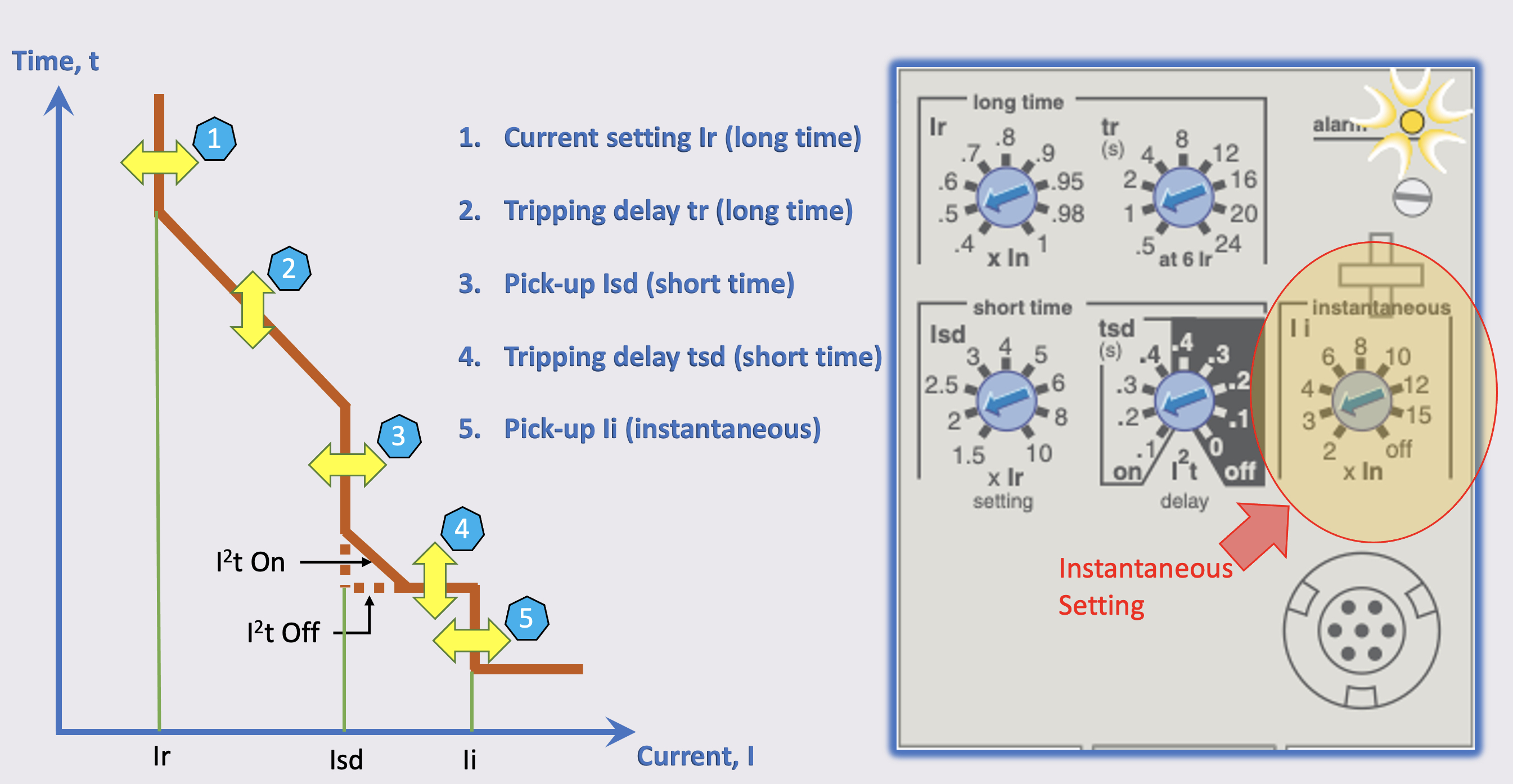
Figure 8.14 Typical settings for integral trip units
The next generation of electronic trips that are available today have much more functionality. They provide more functions of protection but also metering, diagnostics, communication, and remote operation. This may or may not present problems in data collection because gone are the sliders, dip switches and control knobs and these have been replaced with a liquid crystal display and password(s) and/or a key. In Figure 8.15, this illustrates the new layouts.
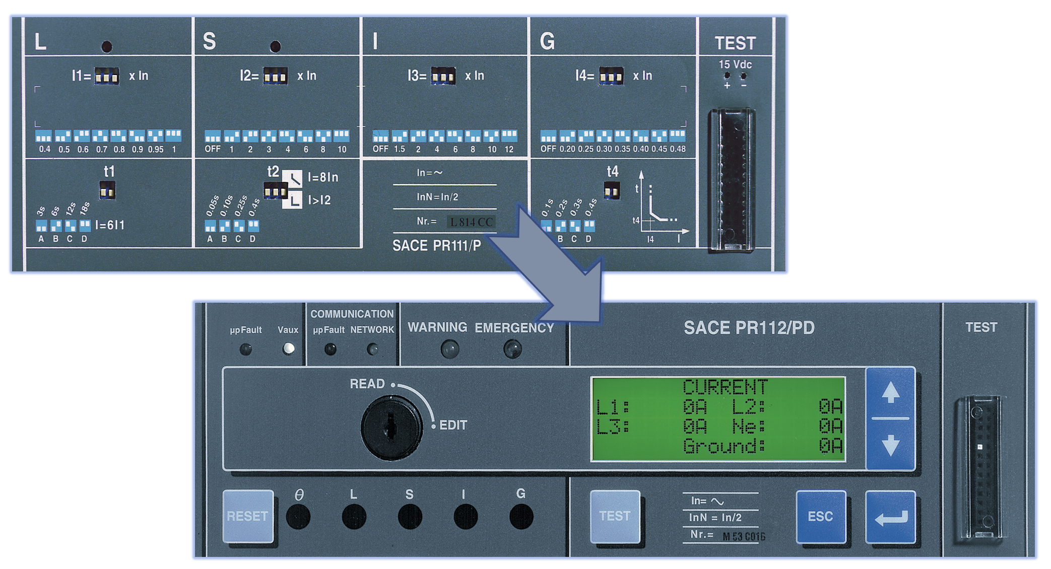
Figure 8.15 New generations of integral trip units
8.4.10.5 Hydraulic Magnetic (Oil Dashpot) Relays
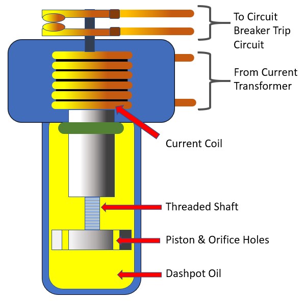
Figure 8.16 Typical dashpot relay
Hydraulic magnetic or oil dashpot over current relays were used extensively on low voltage switch boards and very often as the main incoming circuit breaker from the distribution transformer. As such, they would have a key role in protection of a high value asset and are frequently installed to protect against elevated levels of incident energy for the facility. A diagram of a typical oil dashpot relay is shown in Figure 8.16. As can be seen, a supply from the circuit current transformer is fed onto a current coil which attacks a piston through dashpot oil. Holes in the piston together with the viscosity of the oil acts as a damper and gives the characteristic curve of the relay. The threaded shaft gives further adjustment to the time current characteristic.
The trouble is, with all my experience in the industry, I have rarely found oil dashpots that have been maintained either properly or recently. The oil in the dashpots have been found to resemble sludge rather than viscous mineral oil in some instances. They are also notoriously difficult to obtain the time current characteristics although I have come across generic curves that have been reproduced by design software companies. From a protection point of view, it is quite likely that you may want to disregard them, unless they have been maintained recently and also the tripping characteristics have been proved by way of current injection. If this is the case, then the commissioning report is often a very useful document in determining the disconnection time for an arcing current. A remedy for the duty holder is to have the circuit breakers maintained by a specialist company or to have a new unit retrofitted.
8.4.10.6 Fuses
In electrical power distribution, where fuses are used they tend to be of two particular types in Europe. They are both high rupturing capacity (HRC) fuses to the German NH DIN fuse or the British Standard BS88 fuse and both fall into the category of current limiting protection devices. See Figure 8.17. The is more information given in Chapter 5: Prevention. The fuses are not physically interchangeable, but the characteristic curves are similar. Both NH DIN and BS88 fuses have been around for many years and have a proven reliability record and have remained popular with specifying engineers to this day because of their high fault current handling and minimal energy let-through (I2t). They tend to be the favoured type of protection for utility distribution but are commonly found in industry particularly for motor protection.
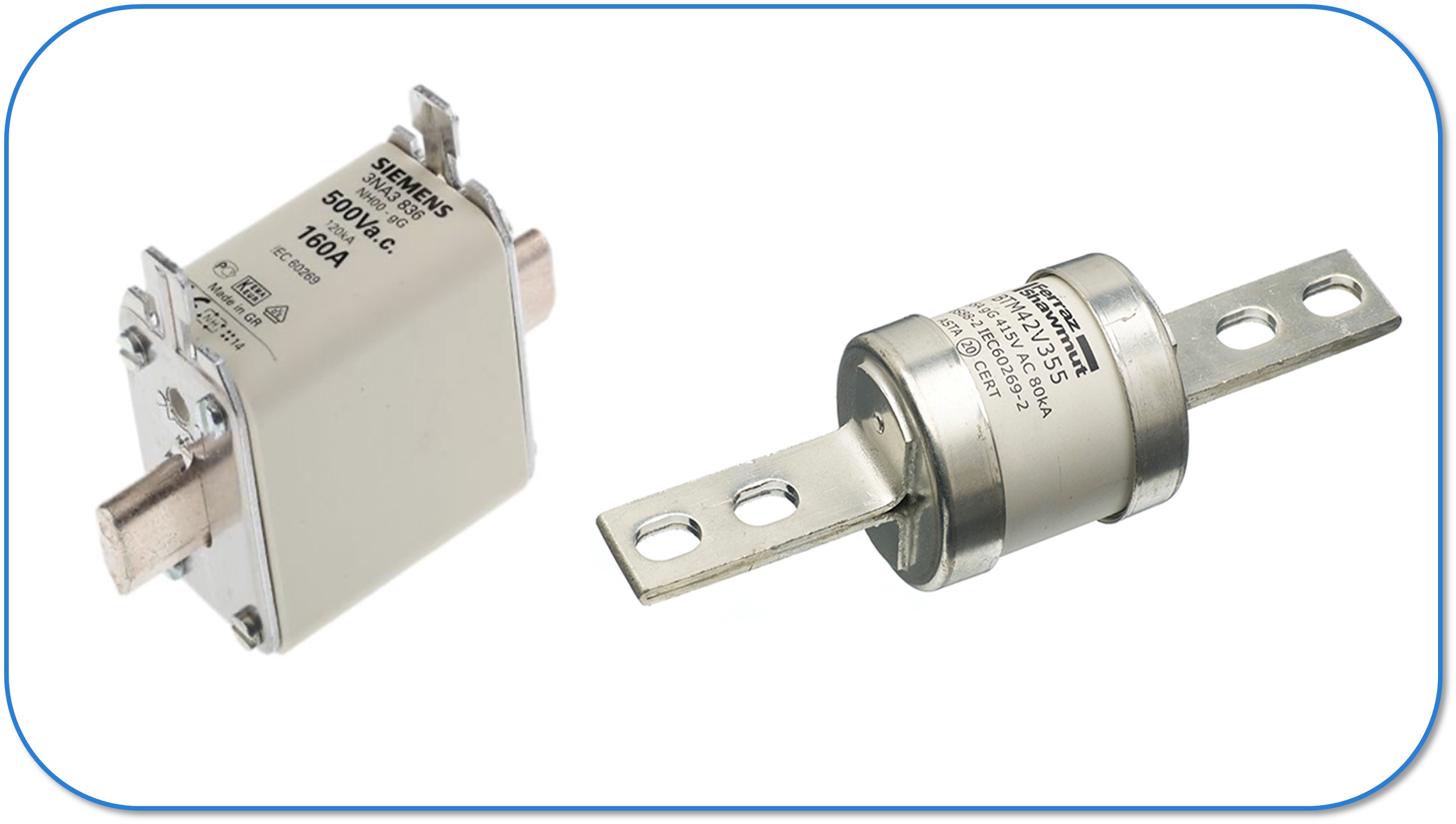
Figure 8.17 HRC Fuses
In terms of data collection, a power interruption may be required in most cases to inspect the fuse body unless separate data is available. Even then, there has to be confidence in the fuse type as motor fuses may be a higher rating in a smaller sized body. There are NH DIN and BS88 fuse interactive time/current characteristic curves appended to this guide for information which include allowances for total clearance times. Other fuse characteristics are generally available by web search and from the main international fuse manufacturers. Be sure to understand what the manufacturer’s time current curve characteristics are displaying. Those curves which display pre-arcing times are unlikely to include any allowance for fuse tolerance or total clearance time.