8.4.10.3 Low Voltage Air Circuit Breaker
Low voltage air circuit breakers are available up to 6300 amperes and many characteristics are similar. The significant difference between MCCB and ACB is in the rated withstand current with ACBs being of a higher magnitude. Because of this requirement, ACBs have more volume to be able to withstand a high over currents over a greater time. Some older ACBs require maintenance in situ and even modern units require post fault inspection of arc chutes and contacts according to manufacturer’s instructions so that is a question to be addressed when collecting data. The vast majority nowadays, tend to have internal electronic trip units built in with multifunctional capability for various protection schemes and monitoring/communication facilities. Carrying out arc flash data collection will throw up other circumstances where external relays such as IDMT protection units and also integral hydraulic magnetic or oil dashpots are present. There are also circumstances where external current transformers have to be taken into account.
8.4.10.4 MCCB and ACB Integral Trip Units
Figure 8.13a is a good example of an integral electronic relay as it shows various overcurrent parameters that are found on MCCBs and ACBs in accordance with IEC 60947-2. It also declares the current transformer ratios which is not usual for integral relays of this class.
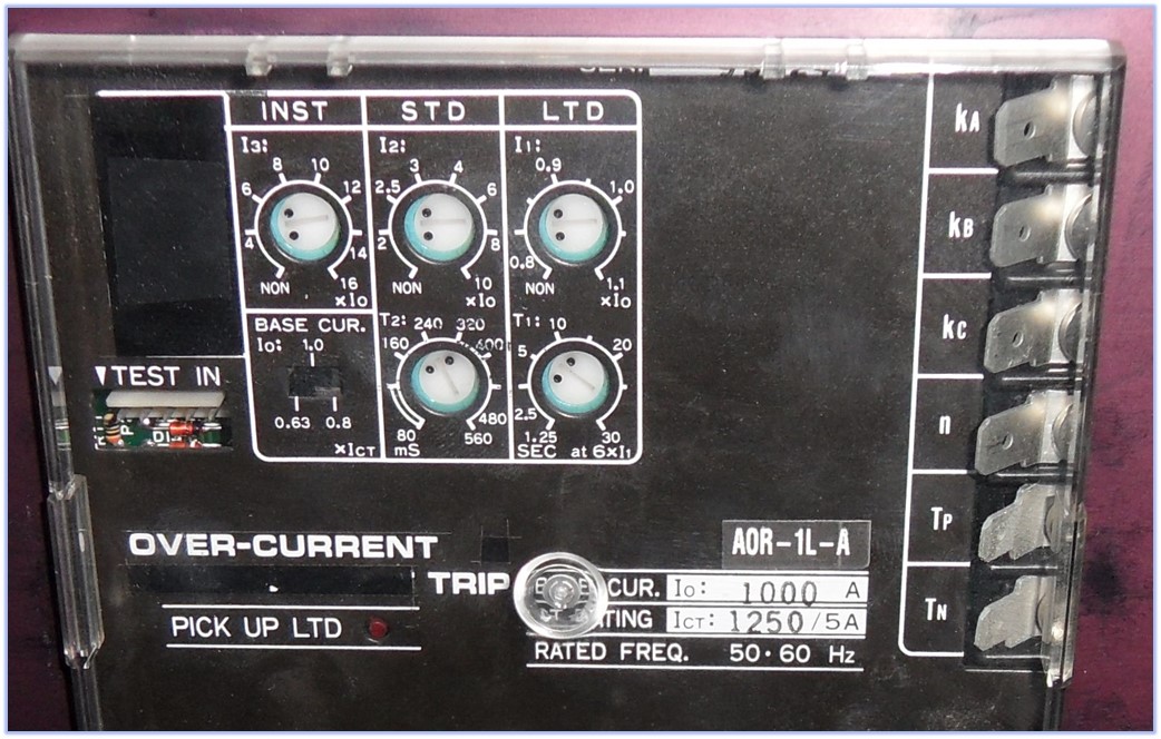
Figure 8.13a Electronic relay
The following is a description of the functions of the relay in Figure 8.13 all of which must be collected at the data collection visit and of course compared to data that may have been received from previous protection studies etc. As you can see for this example, there are frame settings and CT ratios that do not always appear on LV circuit breakers of this class but are important.
- Base current referred to as Io. This is the same as sensor or circuit breaker rating current usually referred to as In on most other units.
- Long-time delay current setting LTD (sometimes referred to as I1 or Ir and are multiples of Io or In).
- Long-time delay time setting (often referred to as tr or t1).
- Short time delay current setting STD (often referred to as I2).
- Short time delay time setting STD (often referred to as tsd or t2).
- Short time I2t setting. This is usually either on or off or sometimes in or out.
- Instantaneous Pick Up current setting INST (often referred to as Ii or I3 or Im).
- Instantaneous Pick Up time setting (often referred to as t3).
- Base current setting (may be a current or a multiple of Io or In).
- CT ratio, not often declared, in this case 1250/5 A.
Base current may be a setting related to the circuit breaker frame size. So, if the frame size of the actual breaker is 1600A (In) then the relay current may have a setting of 1, 0.9,0.8 (or 1600A, 1440A or 1280A for instance) In our case the base current is quoted as Io =1000A. The base current setting of the relay is then 1 or 0.8 or 0.63 times the CT primary rating (Ict).
The following are images of electronic relays which have similar functions to the example given above. I mentioned how important it is to compare protection data collected with previous protection studies and the reason is as follows. In most cases all that is required to alter the protection characteristics is a screwdriver. Although the above relay was behind a hinged door (unlocked) and in a substation, there are many instances where the equipment is open areas such as corridors and does not have a door or a cover. You may also want to explore how future tampering can be avoided for obvious reasons, one of which is that the safety of personnel may be compromised.
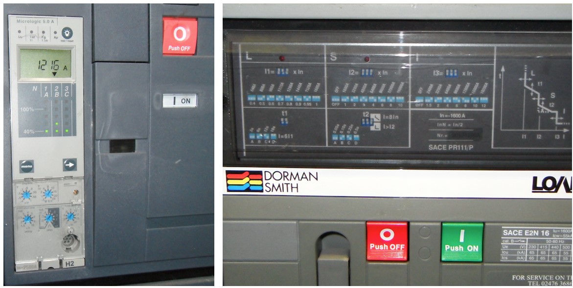
Figure 8.13b Electronic relays