Current transformers also have errors although this is prevalent at lower levels of magnetising exciting current. This is of course, less of an issue at higher currents related to most arcing faults.
We also have to factor in the time for operation of the switchgear. This again can be obtained from manufacturer’s data, commissioning, or timing tests but as a guide for the purposes of an arc flash calculation a generic allowance can be built in. For high voltage switchgear under 15kV, typical operating times are between 40ms for vacuum equipment and 75ms for oil filled equipment. I have used a conservative figure of 80ms which is valid based upon experience and providing that there is a high level of confidence in switchgear operating times and therefore no further safety margin is built in. For older oil switchgear, I understand that some utility technical engineers may even increase this to 100ms. Where there are any doubts further investigations including timing tests may be warranted.
You must ask for records of maintenance and make the point that trip timing tests be carried out if there are any doubts about the frequency of maintenance and or trip timing tests.
8.4.10 Low Voltage Circuit Breaker Characteristics
Low voltage circuit breakers will generally be one of five generic types.
- Miniature circuit breaker – up to 125 amperes single or multipole.
- Moulded Case Circuit Breaker - up to 1600 amperes.
- Air Circuit Breaker with separate protection relay – up to 6300 amperes
- Air Circuit Breaker with integral protection relay – up to 6300 amperes
- Air Circuit Breaker with integral hydraulic/magnetic protection relays.
8.4.10.1 Miniature circuit breaker
The vast majority of miniature circuit breakers that you will come across are built to IEC EN-60989 and IEC EN 60947 that have thermal magnetic protection mechanisms. The following diagram Figure 8.11 shows the typical pickup and clearance time current curves for the circuit breakers manufactured to these standards. No further allowance is required for breaker clearance.
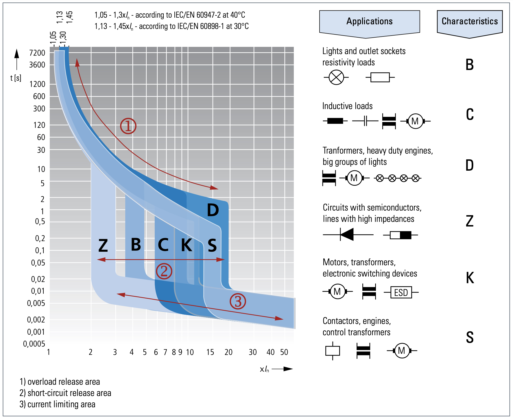
Figure 8.11 MCB tripping curves, image courtesy of Eaton Electric
As you can see, the maximum instantaneous setting is for a type D breaker under IEC 60898 is 20x the current rating (In). For the largest miniature circuit breaker rating of 125 amperes, this will be 125 x 20 = 2500 amperes. This means that all arcing faults under 2500 to 3000 amperes (depending upon the minimum arc current calculation) will clear in approximately one cycle. There may be a possibility that you may come across older types under obsolete standards such as BS 3871 and IEC 898 where the upper limit may be between 10 and 50 times the current rating (In). This is the type 4 miniature circuit breakers under BS 3871 and Type D under IEC 898. This will clearly need checking with the actual circuit breaker type and time current characteristic.
8.4.10.2 Low Voltage Moulded Case Circuit Breaker
Moulded Case Circuit Breakers (MCCBs) are often electromechanical units with thermal magnetic relays producing characteristic curves similar in shape to the miniature circuit breaker. Nowadays MCCBs are supplied with integral electronic trip units as an alternative to thermal magnetic releases, making them much easier to grade with upstream and downstream protective devices. A moulded case circuit breaker is defined as a circuit-breaker having a supporting housing of moulded insulating material forming an integral part of the circuit-breaker. MCCBs can be found up to 1600 amperes. They are very compact and favoured for space saving in factory-built assemblies as outgoing distribution devices although they are sometimes used for incoming circuit breakers from transformers up to 1000kVA.
Moulded case circuit breakers up to 630 A can be found with a current-limiting capability. See Chapter 5: Prevention & Minimisation for further explanation.
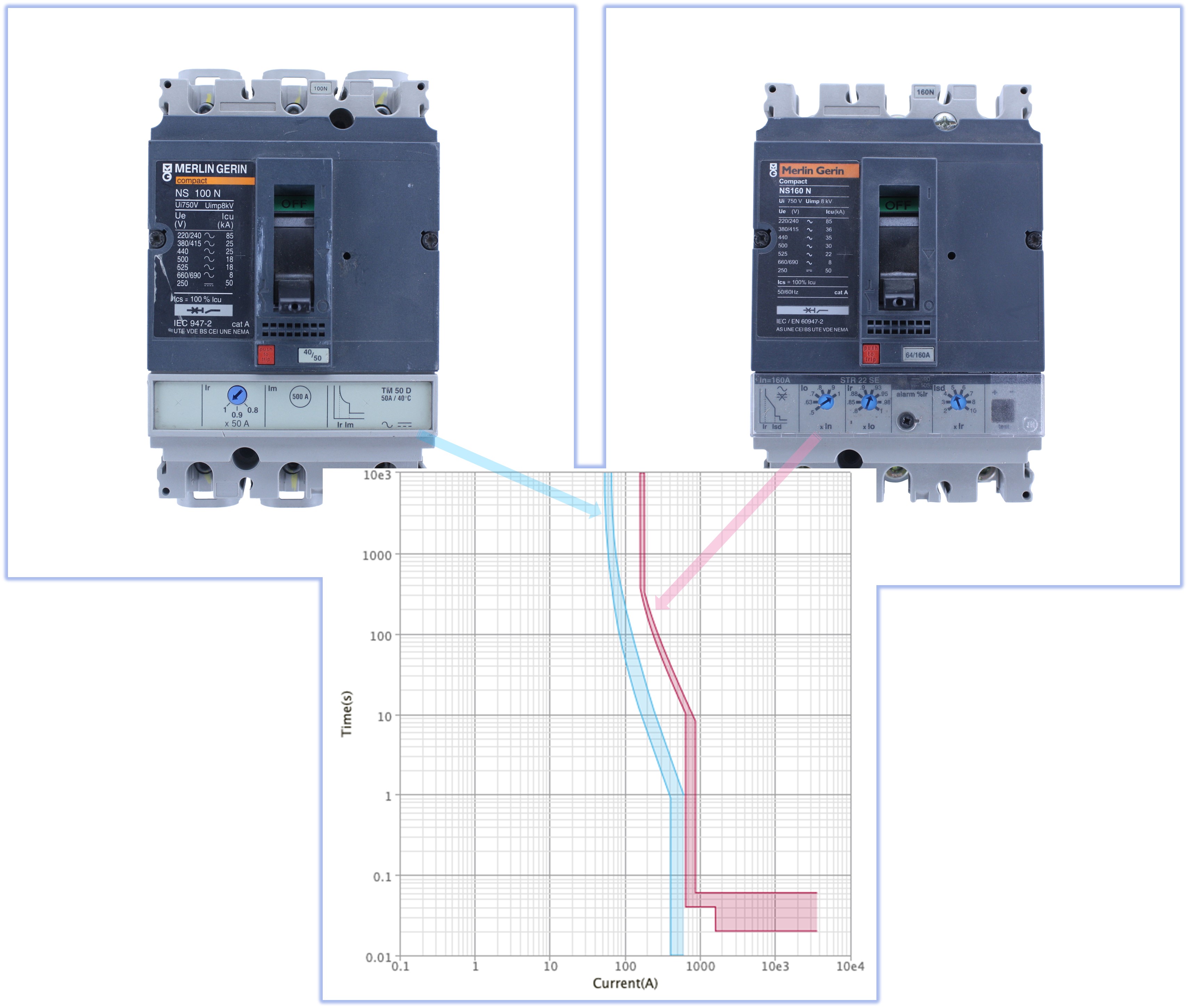
Figure 8.12 Typical tripping curves.
The above images in figure 8.12 show similar moulded case circuit breakers, one with a thermal magnetic trip unit and the other with an integral electronic trip unit. As can be seen, the concave slope of the thermal overload section of the thermal magnetic circuit breaker on the left contrasts with the straight lines created by the electronic trip breaker on the right.