Operation of time fuse links can be explained with the aid of the wiring diagram shown in Figure 8.9. As can be seen, the circuit consists of 3 dual ratio CTs, 2 Direct Acting Trip (DAT) solenoid type overcurrent coils connected in parallel with associated Time Fuse Links (TFL's) and 1 instantaneous earth fault DAT solenoid Coil.
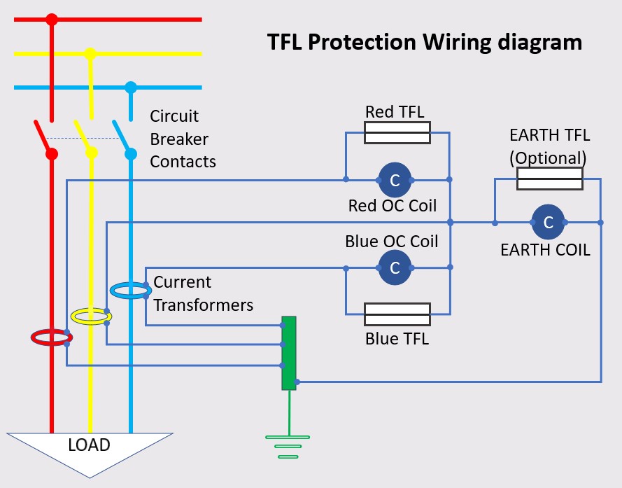
Figure 8.9 TFL Protection wiring diagram
As an example, consider that the circuit breaker supplies an 11,000 volt 1000 kVA transformer. Under normal full load conditions approximately 52 amps will flow in the CT primaries. If the CT ratio is set on 50/5 amp ratio, then approximately 5 Amps will flow in the CT secondary winding. As the overcurrent coils are shorted out by the fuses, no current will flow through the coils. Assuming that there was no earth leakage, the red, yellow and blue phases will balance, and no current will flow through the earth fault coil.
In the event of a phase-to-phase fault of, say, 500 amps, 50 amps would flow through the CT secondaries. This would blow the 15-amp fuse links shunting all of the current through the DAT coils, which would operate and trip the 3-phase circuit breaker.
Two overcurrent coils are required to cover all phase fault combinations, i.e. for a R-Y phase fault, the CB will trip on the red phase coil. Under earth fault conditions, there will be an imbalance between the red, yellow and blue phases, and current will flow down the residual path of the CTs and through the earth fault coil. The unit will trip instantaneously. If a TFL is fitted in parallel with the earth fault coil then the tripping time will follow the TFL characteristics. Alternatively, the fuse can be removed.
The time current curves for the primary circuit current can be easily obtained by taking the TFL characteristic rating and multiplying this by the CT ratio. The range of time current curves in Figure 8.10 below show TFL ratings for a 100/5 A current transformer. Do not forget to add the circuit breaker operation time, for further details see section 8.4.9 Relay Error and Switchgear Operating Time.
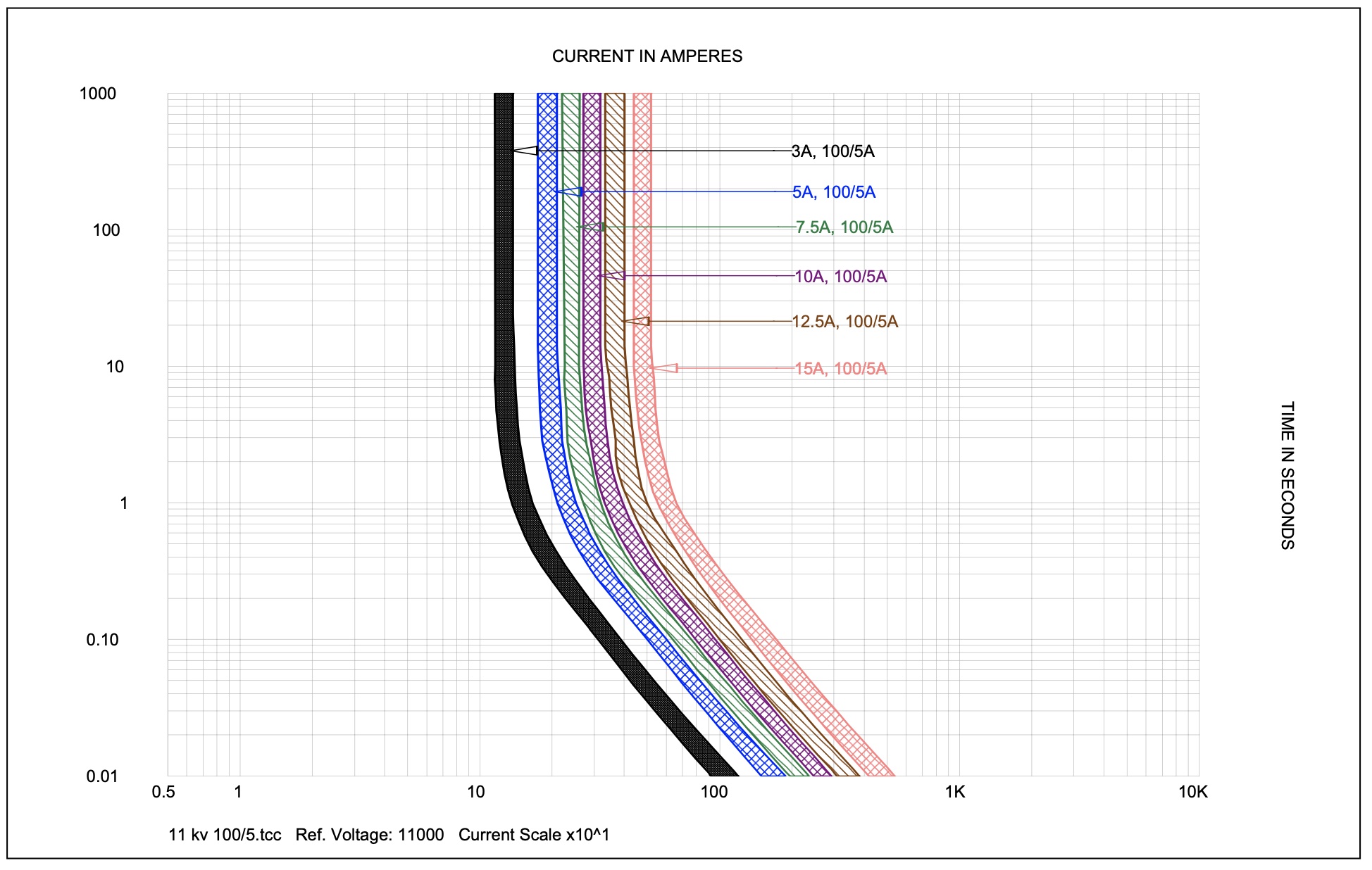
Figure 8.10 TFL Time current curves
8.4.8 DC Tripping Battery Supplies
Locate and check that the tripping battery for the switchgear is working properly and also that it has been maintained. Tell-tale signs of poor maintenance are; no maintenance records, low electrolyte level for non-sealed systems or that battery connections are corroded. The duty holder should be advised that the battery manufacturer’s operation and maintenance instructions should be followed, and in particular, the recommended charging rates should be adhered to. I would suggest that the provision of battery monitoring and alarms to warn of imminent failure of a battery system is essential. Absence of this facility ought to be flagged up to the client as a major non-conformance. Remember, that for powered protective relays, no tripping battery = no arc flash protection!
8.4.9 Relay Error and Switchgear Operating Time.
Do not forget the relay error and switchgear operating time. Trip times are made up of relay reaction time + trip coil delay time + circuit breaker mechanism operating time. All relays have errors in timing which have to be declared if manufactured and tested in accordance with IEC 60255. This will be in the manufacturer’s data sheet, but the following table lists typical values of timing errors for standard IDMT relays.
| Relay Technology | ||||
| Electro-mechanical | Static | Digital | Numerical | |
| Typical % Timing Error | 5 | 5 | 5 | 5 |
| Overshoot Time (s) | 0.05 | 0.03 | 0.02 | 0.02 |
| Safety Margin (s) | 0.1 | 0.05 | 0.03 | 0.03 |
| Typical Grading Margin (s) | 0.4 | 0.35 | 0.3 | 0.3 |