8.4.4 Standard IDMT Overcurrent Characteristics
The standard IDMT overcurrent characteristics are expressed as a mathematical formula according to the IEC 60255-3/BS142 standards and are often the basis of the electromechanical time current curves. The fact that the curves are based on a mathematical formula makes it easy to sense check the relay settings and of course electronic relays use the same curves.
The equation for operating time from IEC 60255 trip curves is as follows:
| t(I) = TMS | { |
|
} |
Where, Is = the current setting and I = the actual current and k and a are the curve type constants. See table below.
There are four curve types used in IEC 60255 (BS 142) which are: standard inverse, very inverse, extremely inverse and long-time standard inverse. For electromechanical relays, the curves are fixed for the particular relay model. So, in other words, if a standard inverse function is required then that is built into the specification of the relay. It will be necessary therefore to check the relay model with manufacturer’s data to determine the curve type.
| Curve Type | Constant | ||
| k | α | ||
| Standard Inverse | 0.14 | 0.02 | |
| Very Inverse | 13.5 | 1 | |
| Extremely Inverse | 80 | 2 | |
| Long Time Standard Inverse | 120 | 1 | |
Note that US relay characteristics to ANSI and IEEE follow a similar format to the above equation but have a further constant L which is added to the expression.
The tools that are available with this guide (through ea-guide.com) provide curves that are based upon all the above IEC 60255 curve types with inputs for current transformer ratios.
8.4.5 Digital Protection Relays
Digital Relays were introduced in the 1980s and instead of analogue circuits, microprocessors were used to implement relay functions. Digital relays use analogue to digital convertor of all measured analogue quantities and use a microprocessor to implement the protection function given previously. Within 10 years both the electromechanical and the solid-state static relays had been mostly replaced by the digital protection relay in industrial applications, although this has proceeded more slowly the electrical utility distribution systems. The perceived complexity of digital relays and a need for simplicity in utility distribution systems may be an explanation of this phenomena. There was also a great deal of nervousness about the millennium bug prior to the year 2000 which no doubt had an effect. (Google the millennium bug to find out what the fuss was all about.)
That apart, digital relays have advantages over electromechanical and the solid-state static relays such as a much higher level of functionality, integration and additional monitoring functions. They also provide flexibility of functions meaning that a single unit can provide many more protective functions other than overcurrent and earth fault. They are generally more accurate, are self-checking and able to communicate with other digital equipment.
8.4.6 Numerical Protection Relays
The next generation on from static/digital relays are the numerical multifunction protection relays which also perform control and monitoring functions. These devices combine the functions of protection relay, data logger and multi-functional display in a single unit creating cost-effective power system management as well as protection. Communications, self-testing, remote operations, energy management and multiple protection functions can be performed in a single unit.
Data collection can be tricky sometimes as there are often password-controlled operations meaning that levels of access can be limited. The possession of a technical manual (usually a few hundred pages) is absolutely necessary as there is nothing generic about the units in the way that they are set or interrogated. That said, the protection, particularly for overcurrent and earth fault follows the same curves and simulates the mathematically generated operating characteristic of earlier generations.
8.4.7 Time Fuse Links or Time Lag Fuses
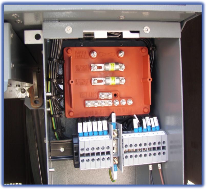
Figure 8.8 Typical time fuse links
Time fuse links are extremely popular particularly for distribution transformer protection particularly in public utility companies for this type of application. This is a very cost-effective means of protection requiring no tripping supply and does create an efficient and a reliable means of disconnecting transformers under fault conditions. The characteristics are easily obtained from the manufacturer or technical standard number which is found on the barrel of the fuse link as seen in Figure 8.8.