8.6 Transformers
Transformers usually have data stamped on the nameplate and you will be unlucky if the minimum information to calculate symmetrical fault level at the secondary terminals is not available. See Figure 8.20 as an example of a typical transformer nameplate.
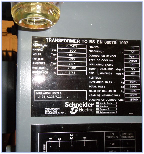
Figure 8.20 Transformer name plate
By minimum information for distribution type transformers, I mean the transformer type, cooling (forced/natural), insulant (oil, air or synthetic fluid), size (rated kVA), primary and secondary voltage and most importantly the voltage impedance as a percentage. Larger transformers may need further information such as automatic tap change mechanisms. As part of the visual checks, I think that it is important to report on the physical condition of the equipment with an eye open for cable box compound leaks, insulant fluid leaks, unusual sounds or smells, security of cable box covers and security locks on off load tap change mechanisms. All these issues could have an effect in the likelihood of a future arcing fault. The transformer X/R Ratio is unlikely to be stamped on distribution transformer nameplates but if you manage to locate the manufacturer’s test sheet then that information will be available. Failing that, the prospective short circuit current calculator tool (available within the store) has generic X/R Ratios for distribution transformers up to 3000 kVA.
8.7 Motors
We know that induction motors can contribute to fault level and need to be taken into account when undertaking short circuit studies. When undertaking complex short circuit studies in accordance with IEC/EN 60909-0 standard, the effect of motors needs to be taken into account if the motor outputs exceed 25% of the total installed. The information that will be required as a minimum will be motor type (synchronous, induction), power factor, efficiency, motor starting, speed control, locked rotor current, sub transient reactance value and X/R Ratio.
Incident energy is affected by motor contribution because the increase in fault level will cause more arcing current to flow for the duration of the contribution. The following simplified diagram Figure 8.21 shows how the contribution from the motor can be approximated by taking the incident energy from the motor and adding it directly to the incident energy from the utility up to the point that the circuit breaker (CB) opens and disconnects the circuit.
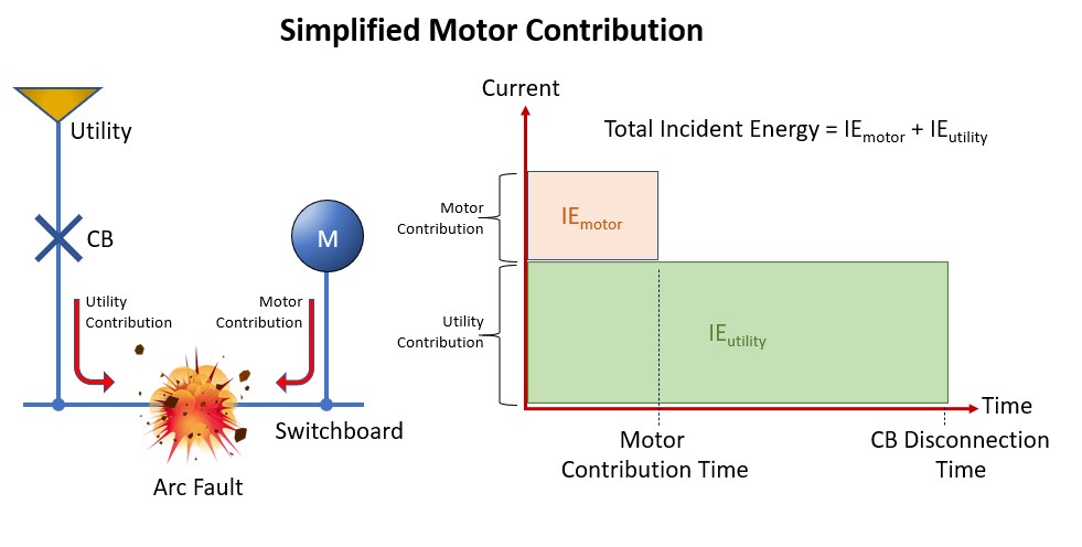
Figure 8.21
The motor incident energy calculator which is available with this guide (ea-guide.com) uses this approximation to allow the user to arrive at a conservative estimate of motor contribution. In terms of data collection, you will need the motor size (kVA, kW or full load amperes). By entering a motor contribution time, which is normally within 100 milliseconds, and an estimate of magnitude of current, often quoted as 4 to 6 times full load current, this will allow for the total incident energy to be estimated.
There was a suggestion in the 2002 edition of the IEEE 1584 Guide for Performing Arc Flash Hazard Calculations, that motors above 50HP (37kW) could be ignored as part of an arc flash study. No such guidance appears in the latest edition and this is where there may be some engineering judgement. You may wish to add all connected motors regardless of size and a acceptable approach will be to add all the motive power and apply it is one large motor. In addition, electronic variable speed drives (VSDs) may be ignored as they block fault contributions from a motor except where the VSD is in bypass mode or where the origin of the fault is in the VSD panel.
If the motor contribution estimate is to determine arc flash incident energy only, then estimates based upon doing “what if scenarios” is, in my view, justified. However, if the objective is to carry out an arc flash study in compliance with the standard IEC 60909-0:2016 (Short-circuit currents in three-phase a.c. systems - Part 0: Calculation of currents) then detailed guidance is given about which motors can be ignored.