8.8 Working Distance
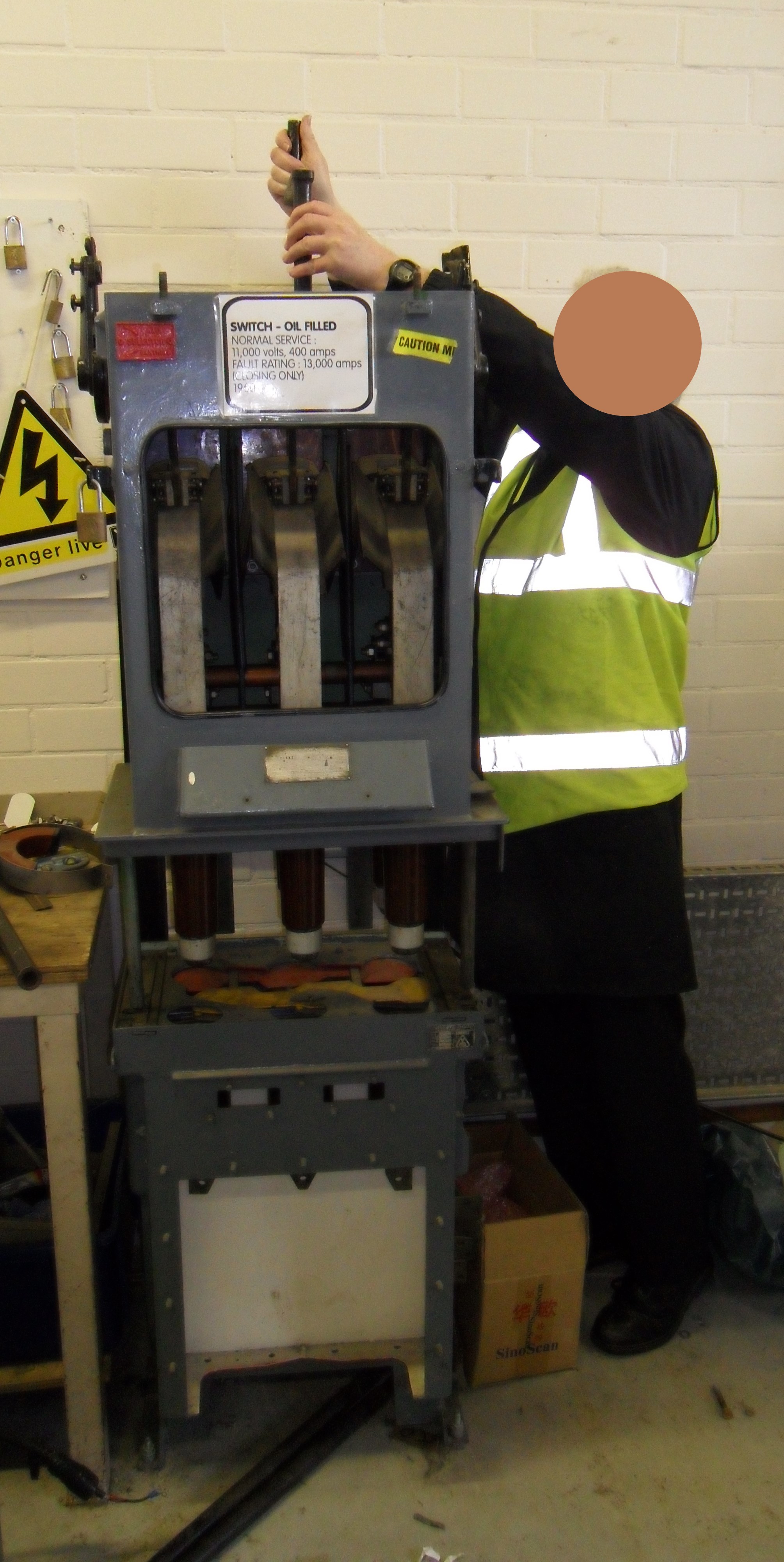
Figure 8.22 Racking an OCB
There is good reason when carrying out a hazard study for a facility to try to standardise on the working distance. This is normally expressed a working distance at low voltage and a second working distance at high voltage. It can reduce confusion when comparing the incident energy at one piece of electrical equipment with another. For instance, you may say that panel A is 10 cal/cm2 at a working distance of 500mm and panel B is 8 cal/cm2 at a distance of 600mm. The fact is that panel B is likely to have a more severe incident energy if the working distance is the same. But actual working distance can change, as we know from this guide small reductions in working distance produce large increases in incident energy. The calculators available with this guide (available within the store) allow for dynamic risk assessments to be undertaken for variations in working distance where different tasks create changes to how close a person is to the arc.
In Chapter 11: Electrical Utilities, there are examples of this, and the image in Figure 8.22 shows one such case. In the IEEE 1584 Guide for Performing Arc Flash Hazard Calculations, there is a standard default working distance of 914mm for operations on 15kV switchgear.
As can be seen in Figure 8.22, the operator is manually racking in a vertical isolatable 11kV oil circuit breaker in a training workshop, hence why parts are cut away. Parts of his body can be seen to be approximately 200mm away from the busbar spouts. This example graphically illustrates that working distance should not be a one size fits all and anyone carrying out a study should be able to recognise these variances and report on them.
8.9 Modes of Operation
It is preferable to get the modes of operations established before leaving site as this could have an effect on the final study. For instance, I remember one site where the client had a maintenance regime which involved the paralleling of transformers. This was achieved by overriding interlock systems that should have prevented such an operation. As it happened, the duty holder did not see the issue as an important one as the duration of parallels were for short periods. By modelling this scenario, not only did it reveal that the low voltage system was overstressed but incident energy levels became extremely high. The other factor to consider was that the likelihood of faults tended to increase post maintenance. This all came to light by discussion on site and by examination of the equipment concerned.
The main thing to remember is that things change, and these changes need to be modelled as scenarios into the final study. It is also good to sense check any assumptions that you may have made with the duty holder so that it becomes a consensus of opinion. The typical scenarios might be as follows.
- Scenario 1 - Base Model – Utility supplies intact.
- Scenario 2 - Utility supplies in maintenance mode.
- Scenario 3 – Emergency Standby generators running in island mode.
- Scenario 4 – Emergency Standby or CHP generators running in parallel.
- Scenario 5 – Transformer parallels and so on.
8.10 Consolidation of Data
When considering large studies, it is prudent at this stage to take stock and check off all the data collected. There may be a list of issues that are unresolved, and if they remain that way, will threaten the smooth expedition of the final study. There will be a great deal of data in a myriad of different formats, so it is important to get it organised. The following is a suggested structure to use when consolidating the data.
- Circuit and equipment data sheets. The data sheets need to be formalised and checked. Missing data can be spotted easily if following the guidance given previously in this chapter.
- Photographic evidence. This will need cataloguing perhaps by substation and may need to be checked by the client for commercial sensitivity.
- Assumptions. Some assumptions may have come about by personal engineering judgement or by agreement with the client/duty holder. It is essential that this is recorded and formally agreed. Examples of assumptions are; modes of operation, working distance, competence of workers, equipment maintenance or inspections and equipment condition (see previous section). This ought to include the actions required to address future changes to network configuration.
- Safety Related Information
- Hazard report forms that have been issued to report serious hazards that are spotted to the duty holder.
- Design and Installation hazards that have been experienced during the data collection process.
- Register of all information received from the site either formally or informally.
- Action planner. Outstanding issues or requests for information will need to be captured in an action planner. This will drive the progress of the project.
When the consolidation process is completed, it is essential that the duty holder/client verifies the data. It is suggested that a package of information containing all of the above plus initial single line diagrams is transmitted to sign off the data collection stage.
- It is vital that the planning and preparation phase is undertaken with some rigor if the overall data collection process is to be successful.
- Get onto the electricity supplier or third-party supplier in respect of the characteristics of supply at the earliest opportunity for a successful outcome.
- Use the analytical tools and calculators with this guide throughout the data collection process to determine worst case scenarios when doubt exists about data interpretation.