8.4.1 Current transformers.
If good records exist, then this will make the collection of data so much easier. Be aware that current transformers (CTs) may have been changed from initial installation for all manner of reasons but most commonly for protection upgrades. The CT ratios will often be stamped inside the small wiring panel of the switchgear or on the rear of the switchgear for feeder protection. See Figure 8.3.
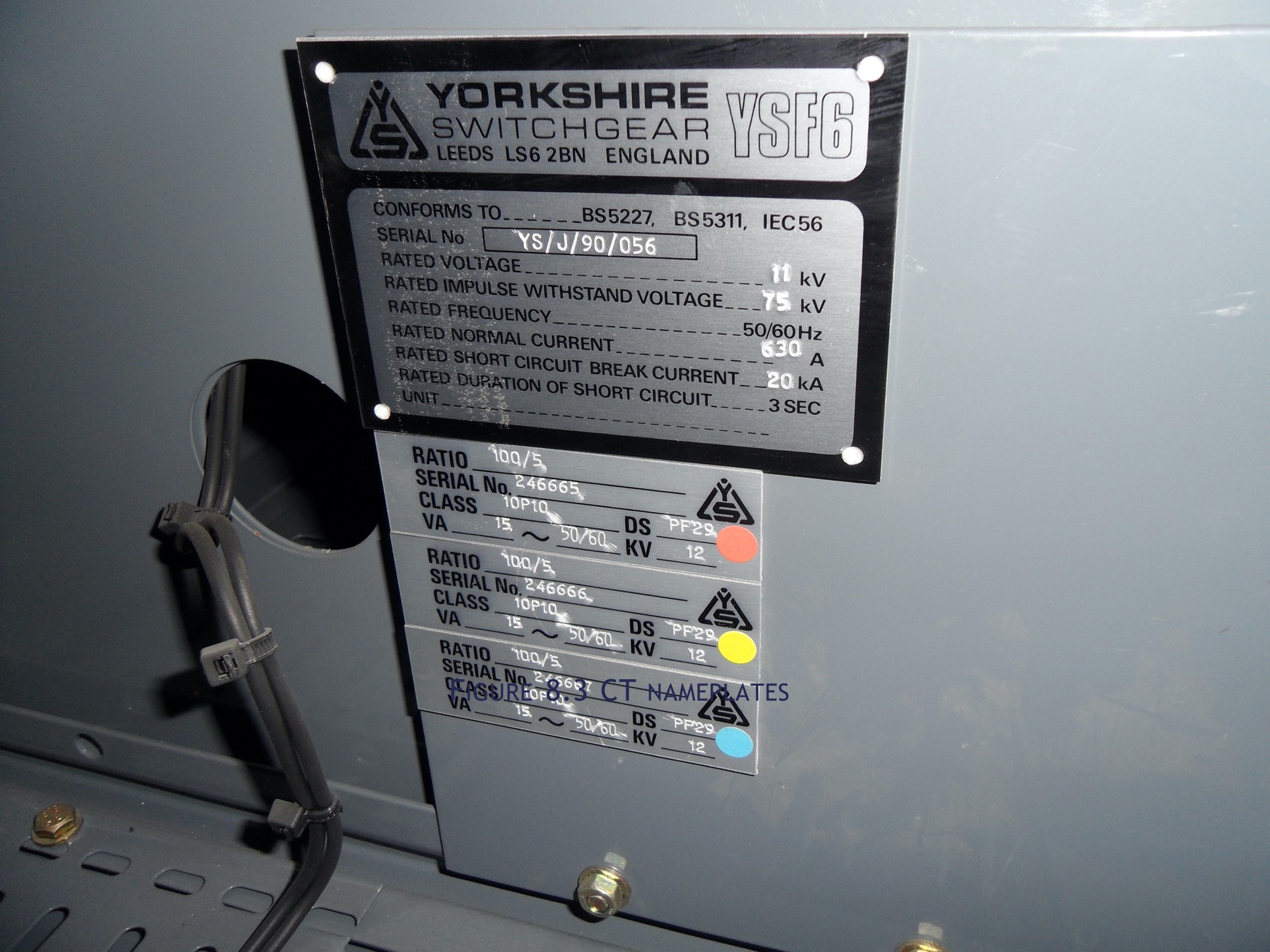
Figure 8.3 Current transformer nameplate
There will also be many occasions where the CT ratios are not marked on the switchgear. What is the breaker feeding? A 400-ampere feeder is likely to have CT primary rated at 400 amperes and 10/11kV transformers up to 1000 kVA are likely to have CT primary rated at 100 amperes or below. Dual wound current transformers are very common, so it is very important to ascertain which winding is used. Further detective work may reveal the CT ratios on metering where these are not separately supplied. The use of a clip-on ammeter to the small wiring can also be compared to metered values for the primary circuit if fitted. If the feeders are at high voltage, then remember the authorisation/competence levels as spelled out previously under the earlier section on “Planning for Safety”.
Always adopt a verification process and sense check what the records say or the markings on the switchgear. For instance, maintenance test, commissioning records or asset registers will usually indicate the CT ratios. If these records are not available because of neglect, then this is a good indicator that the equipment will be unreliable in a fault situation. This should be a prompt to have the necessary maintenance carried out at the earliest opportunity.
8.4.2 Electromechanical Inverse Definite Minimum Time Relays.
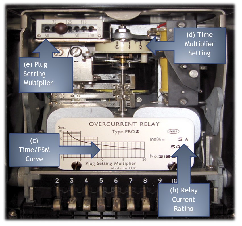
Figure 8.4 IDMT Relay
Induction disc electromechanical relays like the overcurrent model in Figure 8.4 have been around for over a hundred years giving reliable service to the protection of electrical systems. Even when electronic static relays had proved to be reliable and accurate, electromechanical relays carried on being specified particularly with electrical power companies well into the 1980s. As a result, they are commonly found in high voltage equipment and occasionally on low voltage switchgear to this day. The principle of operation is that electromagnets that are fed circuit current, induce current into a moving metal disc creating torque and when great enough, causes the disc to rotate. The disc is retained by a spring and if the magnetic force is great enough, rotation will occur and will operate contacts which in turn will trip the circuit breaker. The disc will rotate at a speed which is commensurate with the magnitude of the current in the measured circuit. The time dial, shown on Figure 8.4 adjusts the distance that the disc has to rotate to close the contacts. The slowest will require almost a full revolution of the disc. This creates the time multiplier setting (TMS) the range of which is usually between 1.0 to 0.1, and the time to operate at the 0.1 setting is reduced to one tenth of that at the 1.0 setting.
The electromagnetic primary winding has a number of tappings that are brought out to the plug setting bridge on the front of the relay, see Figure 8.5.
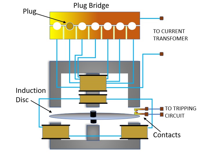
Figure 8.5 IDMT Relay diagram
Dependent upon which plug is used, this will result in the plug setting multiplier (PSM). The plug setting will determine the current at which the relay will start to operate. The tapping range is usually 50%, 75%, 100% (For a 5-ampere relay, 100% means 5A), 125%, 150%, 175% and 200%. Some manufacturers may use 1.5, 3.5, 5, 6.25, 7.5, 8.75 and 10A. For example, for a CT rating of 100/5A, if the relay is set to operate at 5A then the plug setting will be = Relay current setting/5A = 5A/5A = 100%. For a relay to operate at 2.5A, the plug setting (for this example) will be 2.5A/5A = 50%.