Hazard & Severity Calculators
Introduction
The following chapter maps out the online suite of hazard and severity calculators that are available within the store of this site. The purpose of the calculators and accompanying fuse charts is not to provide complex software calculations of entire electrical networks, but rather to allow the reader to be able to do dynamic risk assessments on a case-by-case basis. The author has had in mind that the person who is responsible for risk assessment is not always in possession of intimate knowledge about the supply network parameters. That is why there is a wide choice of methods available each with a varying degree of input information.
List of Calculators
Note: The hyperlinks associated with these calculators will take you to the specific guide page for the calculator.
- IEEE 1584 Incident Energy Calculator (LEVEL 1).
- LV Circuit Breaker Calculator (LEVEL 2).
- Incident Energy HRC Fuse Charts (LEVEL 2).
- LV Devices (Fuses and MCBs) up to 125A calculator (LEVEL 3).
- DC Incident Energy Calculator (LEVEL 1).
- Blast Pressure Calculator (LEVEL 2).
- DGUV Box Test Algorithm Calculator (LEVEL 1).
- Prospective Short Circuit Current Calculator Tool.
- LV HRC Fuse Time Current Curve Tool.
- IDMT Time Current Curve Calculator.
Structure of the Calculator Suite
The following diagram, Figure 14.1, shows where the calculators have originated from. The primary calculator and is based upon the IEEE 1584 Guide for Performing Arc Flash Hazard Calculations. In the same group and based on IEEE 1584 there is a low voltage circuit breaker calculator (No 2), IEC 60928- 2 HRC fuse charts (No 3) and a calculator for devices below 125 amperes (No 4). Then in group B there are two calculators based on theoretical papers which are DC incident energy (No 5) and a blast pressure calculator (No 6). In group C there is a calculator based upon the German DGUV -I- 203-5188 E Guide to the Selection of Personal Protective Equipment for Electrical Work (No 7). Finally, there are three calculators in group D which provide support in helping to obtain fault current information and also to plot time current curves popular in Europe (Numbers 8, 9 and 10).
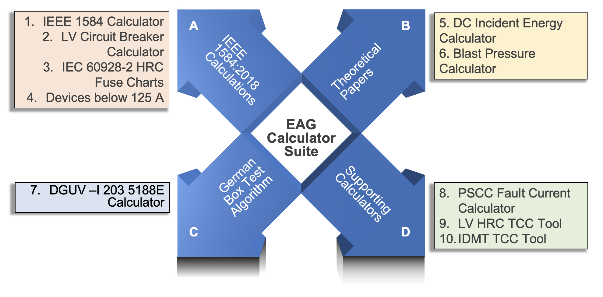
Figure 14.1 Calculator structure
Tiered Approach
In a generic tiered approach, the above calculators and tools are grouped as tier 1, 2 and 3. In the pyramid diagram shown in Figure 14.2, these groups are listed and at the base are the tier 3 circuits which are the most plentiful in most industrial and commercial facilities. As you can see, the only information that will be required is the type and size of the upstream protection and the minimum prospective fault current level. Tier 2 circuits only need actual fault level data and finally, at the top of the pyramid, the actual fault level and a time current curve will be required to return an accurate prediction of arcing current and incident energy. This chapter explains all the tools in detail.
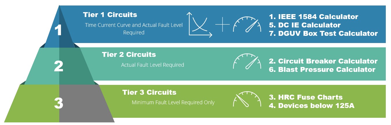
Figure 14.2 Tiered approach