Tier 3 Circuits – Are the low voltage circuits where the upstream device is known but there is no need for a time current curve. All that will be required is the minimum prospective short circuit current at the equipment to be worked upon. Circuits where the incident energy is below 1.2 cal/cm2 can be quickly determined as well as those circuits where there is a dangerous hazard level. These conditions are given in the protective devices that are listed in the calculators and tools that accompany this guide as a separate service. From experience, you may not know what the actual prospective fault current is, but what is usually apparent is what the fault level is not. For instance, if the named range is 2000 amperes and below, a skilled person would be able to determine the likelihood of that being the actual fault level at the equipment. For other instances, there is a prospective short circuit current calculator available.
Tier 2 Circuits – Are similar to tier 3 circuits insomuch as they are low voltage where the upstream device is known but there is no need for a time current curve. In this case, what will be required is the actual prospective short circuit current at the equipment to be worked upon. This is providing that the fault level does not exceed the capability of the device.
Furthermore, the protective devices are circuit breakers but are not listed in the calculators that accompany tier 3 circuits detailed above. In the tier 2 there is an ACB/MCCB/MCB calculator which will allow you to determine an incident energy level based upon the circuit breaker characteristics. The calculator tool works on the basis of a device instantaneous characteristic and produces an actual incident energy level. From this information our risk assessment process, given previously, can be followed which are: “considering if the risk can be eliminated; and if not, making a judgement on whether further measures to prevent or reduce the risk needs to be introduced”.
Tier 1 Circuits - Will require details of the time current characteristic curve for the protective device as well as the actual prospective short circuit current at the equipment. The toolbox has an accurate calculator based up IEEE 1584 Guide for Performing Arc Flash Hazard Calculations, to determine the incident energy for circuits up to 15kV. It also incorporates motor fault level contributions if required.
There is also a DC Incident Energy Calculator which will provide incident energy levels in direct current circuits as part of tier 1.
The above calculators will allow you to recognise extreme danger as part of your risk assessment process and the effort is not too onerous in terms of applying the models.
Also included in tier 1 is the DGUV Box Test Algorithm. Although an incident energy level is not possible using this method, the algorithm is used in some European countries to determine PPE levels. In this case, both a maximum and a minimum fault level will be required as well as a time current curve.
There is also a prospective short circuit current calculator and additional tools to plot time current curves for IDMT relays and European style fuses. The prospective short circuit current calculator also creates maximum and minimum fault levels for use with the DGUV Box Test Algorithm.
14.1 IEEE 1584 Incident Energy Calculator (LEVEL 1)
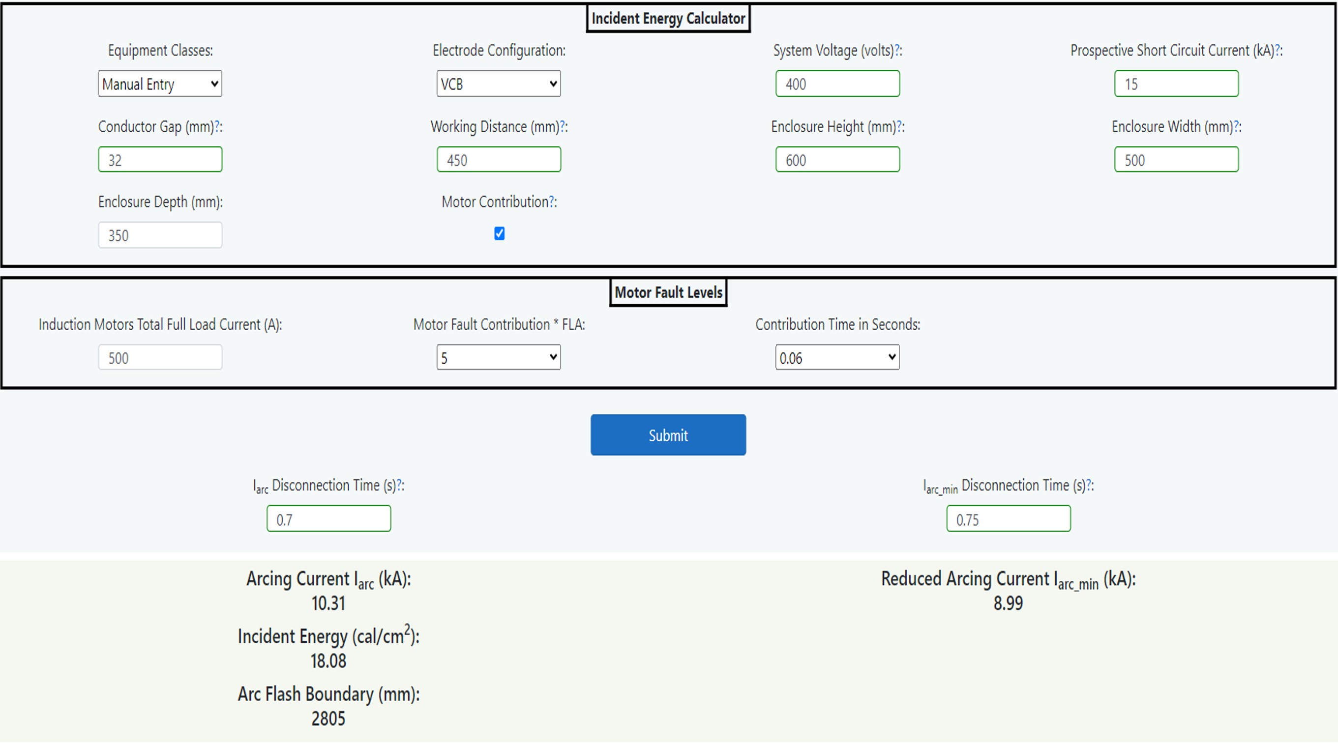
Figure 14.3 IEEE 1584 Calculator
This incident energy calculator is based upon IEEE 1584 2018 Guide for Performing Arc Flash Hazard Calculations. More information can be found in Chapter 4: Prediction. The following sets out how a competent electrical engineer can use the calculator to arrive at an incident energy level at a stated working distance as well as an arc flash boundary which is the distance at which the incident energy level equals 1.2 cal/cm2 (or the threshold of a second-degree burn).
The IEEE 1584 model is valid for systems having:
- Voltages in the range of 208 V – 15000 V, three-phase.
- Frequencies of 50 or 60 Hz.
-
Bolted fault current (Prospective Short Circuit Current) in the range of:
- 700 A to 106,000 A for voltages between 208 and 600 volts.
- 200 A to 65,000 A for voltages between 601 and 15,000 volts.
- Working Distances greater than or equal to 305mm.
- Grounding of all types and Ungrounded. (Earthed and Unearthed systems)
- Equipment enclosures of maximum height and width 1244.6mm. The width needs to be larger than four times the gap between the conductors.
-
Gaps between conductors in the range of:
- 6.35 to 76.2mm for voltages between 208 and 600 volts.
- 19.05 to 254mm for voltages between 601 and 15,000 volts.
- Faults involving three phases only.
- AC (Alternating Current) faults only.