Going through the data field on the form these are described as follows.
Equipment Classes
This is a drop-down field where the user can choose between pre-determined equipment classes or
enter bespoke information for conductor gap, working distance and enclosure size. The pre-determined
equipment classes are listed as follows.
| TYPICAL EQUIPMENT CLASSES DEFAULT VALUES | CONDUCTOR OR BUS GAP | WORKING DISTANCE | TYPICAL ENCLOSURE HEIGHT | HEIGHT | WIDTH | DEPTH |
| 15kV Switchgear | 152 | 914 | LARGE | 1143 | 762 | 762 |
| 15kV MCC | 152 | 914 | LARGE | 914 | 914 | 914 |
| 5kV Switchgear | 104 | 914 | LARGE | 914 | 914 | 914 |
| 5kV MCC | 104 | 914 | LARGE | 1143 | 762 | 762 |
| Low Voltage Switchgear | 32 | 609 | MEDIUM | 660 | 660 | 660 |
| Low Voltage Switchgear (Shallow) | 25 | 457 | SMALL - SHALLOW | 508 | 508 | 508 |
| Deep LV MCCs and Panel Board | 25 | 457 | SMALL | 355 | 304 | 203 |
| Cable Junction or Joint Box | 13 | 457 | SMALL | 355 | 304 | 203 |
| Cable Junction or Joint Box (Shallow) | 13 | 457 | SMALL - SHALLOW | 355 | 304 | 203 |
Typical Equipment Classes
Selecting any of the typical equipment classes will return the corresponding values of conductor gap, working distance and enclosure height width and depth. It is the user’s responsibility to verify that these values are reasonable as they can vary.
If the Manual Entry item is chosen, then a second control panel appears called the Manual Entry Table, at which point you can enter bespoke values of conductor gap, working distance and enclosure height width and depth manually. All the units are in mm.
Electrode Configuration
There are five different electrode configurations, and this field is a drop down list giving choices as
follows:
- VCB: Vertical conductors/electrodes inside a metal box/enclosure.
- VCBB: Vertical conductors/electrodes terminated in an insulating barrier inside a metal box/enclosure.
- HCB: Horizontal conductors/electrodes inside a metal box/enclosure.
- VOA: Vertical conductors/electrodes in open air.
- HOA: Horizontal conductors/electrodes in open air.
Chapter 8: Data Collection describes which electrode configuration to use as the choice will determine not only the arcing current but also the incident energy & arc flash boundaries. The following diagrams (Figure 14.4) are reproduced here to assist.
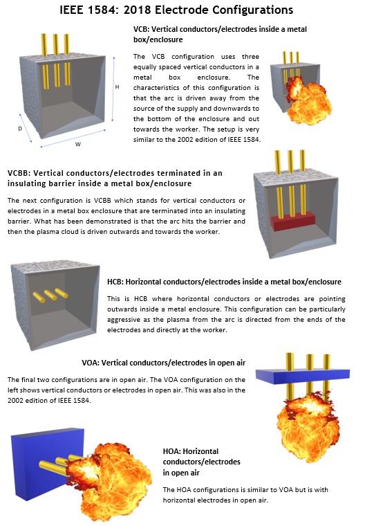
Figure 14.4