Calculation Flowchart
The flowchart shown in Figure 14.21 shows the logic used by the calculations. The data entry boxes,
shown in green, correspond with the descriptions shown and the short circuits currents and R/X values
mentioned previously are shown in the first three boxes. The orange boxes correspond to the
calculations for which a description is given below.
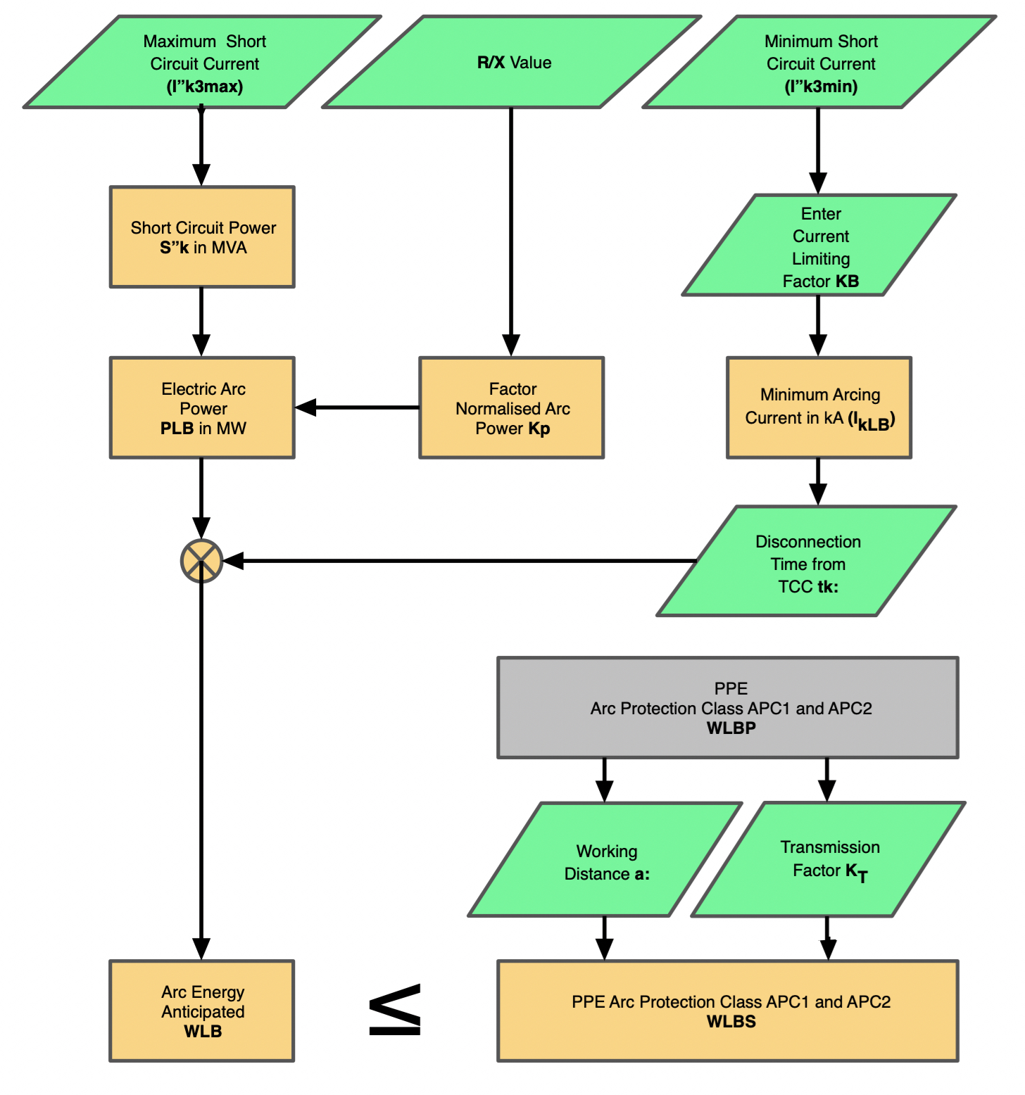
Figure 14.21 Flowchart
Electrode Gap in mm (d) – DATA ENTRY
This is the minimum gap between the conductors measured in millimetres.
Current Limiting Factor (KB)– DATA ENTRY
The current limiting factor is simply applied to the minimum short circuit current I”k3min to produce an arcing current.
Minimum Arcing Current in kA (IkLB) - CALCULATED
This is calculated from the current limiting factor and minimum short circuit current.
Disconnection Time in seconds (tk)– DATA ENTRY
This is the time to clear the minimum arcing current above and is obtained from the time current curve
of the upstream protective device. See Chapter 4: Prediction.
Short Circuit Power in MVA (S”k)- CALCULATED
This is simply the maximum available power based upon the maximum short circuit current I”k3max and
line voltage. (√3VI"k3max)
Normalised Arc Power Kp - CALCULATED
The normalised electric power is a factor which accounts for the arc formation and geometry of the
conductors. For worst case conditions it is calculated from the equation:
| kpmax = |
|
Electric Arc Power PLB (MW) - CALCULATED
Electric arc power Is the power transferred to the arc based upon the Short Circuit Power (S”k) times
the normalised electric power (Kp).
Arc Energy (Anticipated Value) WLB - CALCULATED
The anticipated value of arc energy takes into account the electrical arc power and the disconnection
time. WLB = PLB x tk
Arc Protection Class of PPE WLBP_APC1 & WLBP_APC2– GIVEN VALUES
The arc protection class of PPE is given from the DGUV guide, and the latest figures are WLBP_APC1 =
168 kJ and WLBP_APC2 = 320 kJ. This value is the protection level of APC1 or 2 at a distance of 300mm.
(The sample set up distance for the box testing of PPE)
Transmission Factor KT – DATA ENTRY
The transmission factor is derived from whether the arc is enclosed (in a box), semi enclosed, in air
but against a rear wall or in open air. A diagram of the three configurations is shown in Figure 14.22.
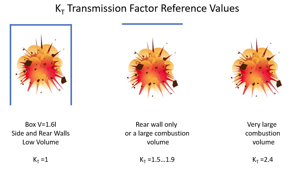
Figure 14.22 Transmission Factors
Working Distance (a:) - DATA ENTRY
Distance in millimetres from the arc to the person’s body (torso).
Protection Level of Clothing WLBS_APC1 and WLBS_APC1 - CALCULATED
Protection level of the clothing is obtained by extrapolation of the box test parameters to the arc
location.
| WLBS = Kt x | ( |
|
) | 2 x WLPB |
PPE Selection
This is the final step which is to compares arc energy (anticipated value) WLB with the protection level
of the clothing WLBS. Protection is given if the following is true.