14.8 Prospective Short Circuit Current Calculator Tool.
Introduction
The prospective short circuit current calculator tool is useful to provide an estimate of the prospective short circuit current at the equipment where incident energy hazard evaluation is to be carried out. By using the calculator, the prospective short circuit current can be determined which can then be used in the Incident energy calculator.
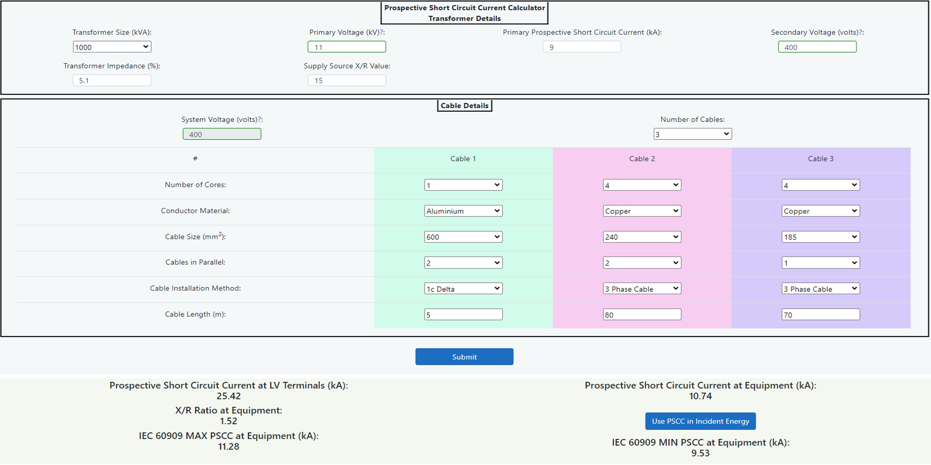
Figure 14.23 Prospective short circuit Current Calculator
The tool is based upon the impedance method which will provide an RMS symmetrical short circuit current which can be inputted directly into the IEEE 1584 Incident Energy Calculator. There is also a separate output of maximum and minimum fault currents in accordance with IEC 60909 Short-circuit currents in three-phase AC systems. This will be required for the DGUV-I 203-078 German Calculator if required.
The limitations are:
- Three-phase short circuits up to a maximum secondary voltage of 600 volts.
- Symmetrical three-phase fault current only.
- Single radial circuits only.
- Main’s contributions only. Motor contribution can be included when using the IEEE 1584 Incident Energy Calculator.
- The cable resistance and reactance values are generic, users must satisfy themselves that these are a reasonable estimate.
The following diagram Figure 14.24 shows a single line representation of the components of the Prospective Short Circuit Current Calculator. In this case the equipment to be worked upon is represented by switchboard SB3 but this could alternatively be SB1 or SB2 simply by omitting the cable 3 or cables 2 and 3 respectively. The calculator should be used when equipment being studied has an upstream transformer device as the supply source or as an alternative, the transformer may be omitted to use the cable calculators only.
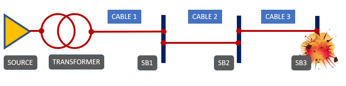
Figure 14.24 Single line diagram
Transformer
The transformer short circuit calculator, shown below, can be used to determine prospective short circuit current and X/R ratio at the low voltage terminals of a transformer. The generic transformer X/R ratios are taken from several sources of information including different manufacturers and also IEEE 242 which suggests typical levels. The author has taken these values to create a table of reasonable averages for distribution type power transformers based upon voltages up to 20kV primary and up to 600 volts secondary. Transformers will all possess different specifications due to the nature of their manufacturing process, so a higher degree of accuracy is possible by obtaining the original transformer specification. The calculator is, however, much more accurate than taking manufacturer’s estimated LV fault data based upon infinite HV impedance and average % impedance values.
To use this calculator:
- Inspect the transformer to be assessed taking note of kVA size, primary voltage, % impedance and secondary voltage. See Chapter 8: Data Collection for further guidance.
- Enter this information into the calculator by selecting/inputting the relevant data into the data entry fields.
- Contact the local utility supplier to determine the actual prospective short circuit current of the supply. It is always good practice to obtain the minimum fault level also as this could lead to a potentially longer disconnection time in the case of an arc flash.
As indicated in step 1 above the transformer impedance can be obtained from the transformer nameplate. Failing that, the following table 14.26 shows some standard impedance levels that can be used with a caution to apply some sensitivity validation (or what if analysis) to any incident energy levels obtained as a result.
| kVA Rating of the MV/LV Transformer | <630 | 800 | 1000 | 1250 | 1600 | 2000 |
| Impedance volts % | 4 | 4.5 | 5 | 5.5 | 6 | 7 |
Figure 14.26 Standardised short circuit voltage for public distribution transformers – Source Schneider Electric.