The calculator uses the following table, Figure 14.27 of average X/R ratios for transformer kVA sizes as described previously.
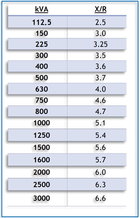
Figure 14.27 Average X/R Ratios for Transformer kVA sizes
The calculator will then produce results for the prospective short circuit current and the X/R ratio at the Low Voltage terminals. These values can then be used in the fault current level calculator to make allowances for cabling between the transformer and the equipment.
Please note that this tool is valid only for transformers up to 20kV on the primary side and up to 600V on the secondary side only. For transformers above either of these values, contact the manufacturer for X/R values. Note also that this calculator assumes a typical high voltage source X/R value of 15. Although this is a fair assumption for most situations, this still would require consideration to ensure that the calculator’s assumptions are correct for the specific transformer being assessed.
This calculator should be used when equipment being studied has an upstream transformer or low voltage mains from a utility company as the supply source. By using the calculator, the prospective short circuit current can be determined which can then be used in the incident energy calculator.
Cables
The calculator tool shown is useful to provide an estimate of the prospective short circuit current at the equipment based upon Schneider Electric Cahier technique no. 158 “Calculation of short-circuit currents” by Metz-Noblat, Dumas and Poulain. This is a very useful technique to provide conductor resistance and reactance values based upon material resistivity calculations and average reactance values. When calculated to this method, the results are very similar to the generic cable resistance for non-flexible cables (stranding class 2) found in BS EN 60228 standard on conductors of insulated cables. The tool requires information about the system voltage, source prospective short circuit current, X/R ratio and details about the cables between the supply and the equipment itself. The prospective short circuit current is based upon the cable temperature at 20℃.
The prospective short circuit current at the equipment can be found by:
- Determine the system voltage, source prospective short circuit current and the X/R ratio and enter the data into the calculator. This is not required if the transformer calculator has been used above.
- Assess the cabling between the source and the equipment noting conductor material, number of cables in parallel, number of cores for each cable, cable size and length. Enter the data into cable 1 by selecting from the drop-down lists provided. See Chapter 8: Data Collection for further guidance.
- If there are multiple cable types in series from the source to the equipment, take note of each cable’s parameters as in step 2 and enter the extra cable data into the optional cables 2 and 3 by selecting the relevant drop-down list options provided.
After the above steps have been followed, the tool will generate an estimated prospective short circuit current at the equipment which can be used in the incident energy calculator or other estimation modules provided.
The cable resistance and reactance values are generic and whilst this will allow for a reasonable estimate, cable manufacturing processes and materials will inevitably lead to variances. The generic values are given below in Figure 14.28 and users are advised to satisfy themselves of their accuracy.
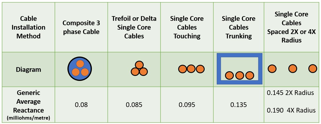
Figure 14.28 Average Reactance Values – Source Schneider Electric.
As can be seen, the reactance values can vary widely with different installation methods and any electrical engineer who is carrying out retrospective system studies needs to be aware of this fact.
The resistance values are based up ρ0 = resistivity of conductors at 20℃ = 0.01851 Ω mm2 /m for copper and 0.02941 Ω mm2/m for aluminium. For loaded conductors in order to obtain a minimum short circuit current in accordance with IEC 60909, see later paragraph, a multiplication factor of 1.25 has been used. This factor will return a value which is in line with a conductor operating temperature maximum of 90℃ which should be conservative for power systems.
Please note that this tool is only valid for system voltages between 208 – 600V (3 phase AC) and a source prospective short circuit current of between 500 A to 106 000 A.