Operating Logic
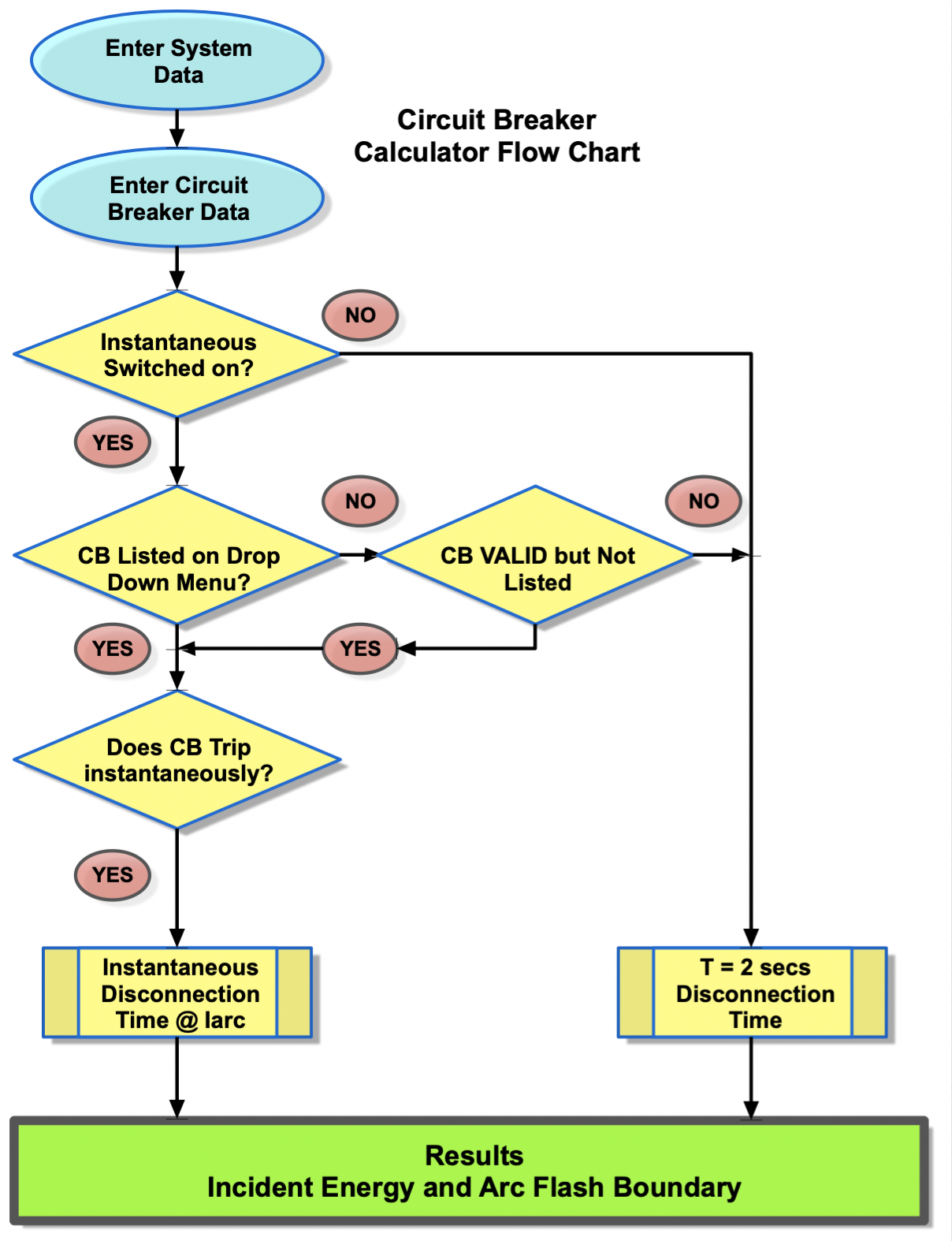
Figure 14.11 CB Calculator Flowchart
The calculator flowchart, Figure 14.11, shows the input sequence and the operating logic.
To use the calculator, first examine the upstream circuit breaker settings and determine the prospective short circuitcurrent at the equipment to worked on or nearby. Verify that the circuit breaker is listed or that it complies with the tolerance values given in the drop-down field “Circuit Breaker”.
Enter the working distance (mm) which is the distance from an arcing source to the torso and/or head.
Determine the electrode configuration and conductor gap distance (mm), more information on electrode configuration is given in Chapter 8: Data Collection.
Enter the circuit breaker rating in amperes and the instantaneous pick-up level which has to be given as a multiplier of the rating. Verify that the instantaneous section or setting is switched to on and select YES from the drop-down menu. Select NO if the instantaneous setting is switched off.
A typical circuit breaker integral trip unit is shown in Figure 14.10. From the information given the calculator will produce an incident energy level and arc flash boundary based upon either, instantaneous operation of the circuit breaker or a two second maximum disconnection time. IEEE1584 Guide 2018 says “If the total protective device clearing time is longer than two seconds, consider how long a person is likely to remain in the location of the arc flash. It is likely that a person exposed to an arc flash will move away quickly if it is physically possible, and two seconds usually is a reasonable assumption for the arc duration to determine the incident energy.”
Note: you must ensure that the short circuit rating and maintenance of the circuit breaker is correct and fit for purpose.
Circuit Breaker Listings
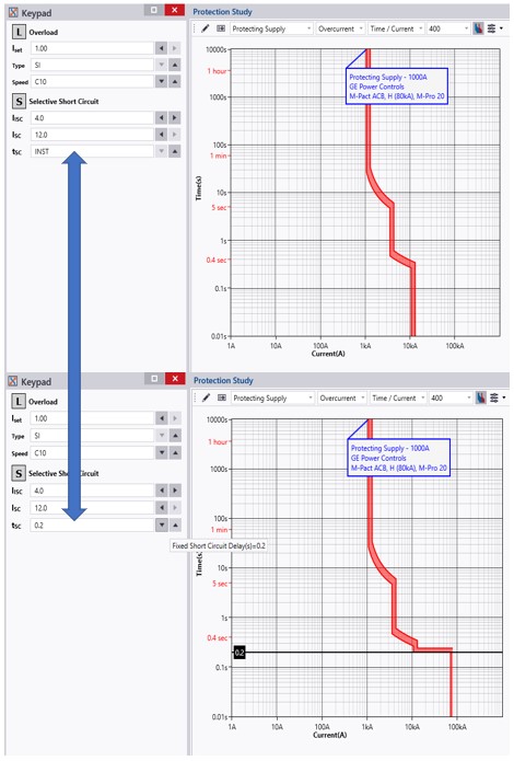
Figure 14.11 Example of time delay setting
The circuit breaker listing library contains over 8000 common circuit breakers in use in Europe. In order for the circuit breakers to be listed, they will pass the following criteria.
- The instantaneous element will be adjustable.
- The clearance curve tolerance will be no greater than 25% as explained previously.
- The minimum operation time for the circuit breaker will be no more than 0.08 seconds when operating in the instantaneous zone.
If the circuit breaker is not listed, then you can check that the parameters fit the above criteria and click the checked box. If there is no adjustable setting for the instantaneous setting, then check the manufacturer’s data.
The other thing to look out for is that some circuit breakers provide a selective short circuit function with a time delay setting as in this example given in Figure 14.12. Make sure that the time delay is disabled and, in this case, tsc should be set to INST. As can be seen in this example, the selective short circuit setting can be set to instantaneous in which case there will be no intentional delay or, alternatively, a delay can be introduced.