12.8 Arcing Damage to a Primary Substation
When I was an electrician aged twenty-one, I was to carry out the installation of low voltage transformer tails in a steelworks in Sheffield. Because the work was in a live high voltage substation, I would need to have an access authorisation from the company. It fell to the district engineer to carry out an assessment that would be necessary to issue the authorisation. The familiarisation and assessment involved the district engineer driving me to various substations and pointing out particular hazards and safety features. One of the substations that we visited had recently had a fault which was quite extraordinary in nature, or so I thought at the time. There was a local transformer which fed a low voltage switch board a good distance away using four large single core cables which were bunched together. A fault had developed at the low voltage board and the protection, which was on the high voltage side of the transformer, failed to operate. The result was that the cables burnt for many metres along their length as a result of arcing. The arc was finally extinguished at the point at which the tails went through a wall and all that was left were stumps sticking out of the hole. The substation was a large structure, but everything was covered in black soot. This had a profound effect on me and may explain why I have always been cautious about the issues surrounding the design and protection of transformer low voltage tails. The following story highlights this caution some 35 years after this experience.
12.9 Hospital Design Mistake
I carried out a fault level study, protection coordination study and an arc flash study for a large teaching hospital about 10 years ago. Subsequent work included an upgrade from 6.6KV to 11kV and further protection coordination studies. It was a very old site and much of the electrical installation comprised of legacy switchgear. That said, huge amounts of effort had been put into upgrading electrical supplies on site sometimes as the result of new construction. One major project was a new critical care block. The electrical supplies to the block comprised of 2 MVA transformers and associated low voltage switchboards plus generator backup. I was somewhat surprised to see that a voltage optimisation unit had been installed into the circuit between each transformer and the main switchboards. See Figure 12.5. (Note: Voltage optimisation is a term given to the systematic controlled reduction in the voltages to reduce energy use, power demand and reactive power demand) I was surprised for a number of reasons:
- Why would someone want to reduce the voltage on a brand-new electrical installation which had presumably been designed properly so that all equipment and lighting would operate at an optimum level?
- The voltage optimisation units were operating at 400 volts and had no additional short circuit protection apart from that afforded on the high voltage circuit breakers on the primary side of the transformers. This zone is often referred to as a blind spot for protection any fault would have to be seen through the impedance of the transformer windings by the conventional over current high voltage protection relays.
- I knew that any additional impedance that was inserted into low voltage transformer tails could have a detrimental effect on the disconnection time. This was regardless of any advancement in the understanding of arc flash calculations.
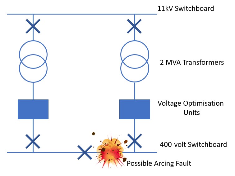
Figure 12.5 Showing location of VOUs
The fact was, that the voltage optimisation units had already been installed and I therefore began to use the nameplate data on the voltage optimisation units in order to model them into my studies. Although an impedance was stamped onto the nameplate I checked with the manufacturer and ascertained that the impedance of the units was dynamic and not fixed. This had a marked effect on the downstream fault level depending upon the settings. Following several discussions with the manufacturers, it was felt that the best way to model the units into the software was to present them as a one to one transformer. In this way, various scenarios could be developed in order to simulate different impedance values. The results were frankly quite startling, and I calculated that the incident energy at the low voltage switchboards could be as much as 73 cal/cm2 against 5.1 cal/cm2 for not having the units in service. The additional impedance of the voltage optimisation units was like increasing the length of the transformer low voltage tails by a factor of three.
I am afraid that despite receiving contrary impedance values and various assurances about how the internal impedance would act under load, the local healthcare trust was unconvinced, and the units were stripped out. I even enlisted the assistance of a well-respected professor of electrical engineering to help make sense of the restricted technical data given by the manufacturers. The information was withheld because of “commercial sensitivity” so we were effectively dealing blindly with a “black box”. The fact was the installation of the units was a very costly mistake but the correct decision to strip them out was made in my view. After all, the units fed the critical care block involving the life or death of very poorly patients.
What I learnt from this experience, was that undertaking the studies had uncovered a design flaw which could have had serious consequences. I would urge anyone undertaking design on large power systems to consider not just zero impedance short circuit faults but arcing faults as well.