To consider the point further I am going to use the example of a low voltage circuit protected by a simple 400 ampere moulded case circuit breaker with an adjustable instantaneous pick up of between 5 and 10 times the circuit breaker rating. That is, the instantaneous trip can be set at between 2000 amps and 4000 amps. Illustrated in Figure 5.1 is a time current characteristic curve for the device which has an opening and a clearing characteristic.
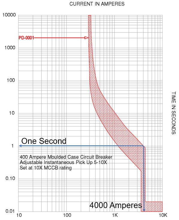
Figure 5.1
We are interested in the clearing characteristic for the purposes of this example which is the line to the right-hand side of the curves. If we predict the arcing current to be 4000 amps and the instantaneous setting of the circuit breaker is at 10 times (4000amps), the time for trip will be of the order of 1 second. Should an arc flash occur and be sustained for this period of time a large amount of thermal energy will be expended in the arc resulting in damage and injury depending upon the design of the equipment. Based upon arc flash calculations for enclosed low voltage equipment this could be in the order of around 11 cal/cm2. A solution, should protection coordination permit, will be to lower the instantaneous setting to 6 times the circuit breaker rating or 2400 amps.
As you can see from figure 5.2, the resulting time to trip will be in the order of 0.02 seconds or one cycle at 50 Hertz. We have previously discussed the relationship between time and incident energy and this reduction in thermal energy is directly proportional to the reduction in tripping time. So, this simple measure, which can be accomplished by a screwdriver in this case has reduced the incident energy by a factor of 50 (1/.02) to 0.22 cal/cm2.
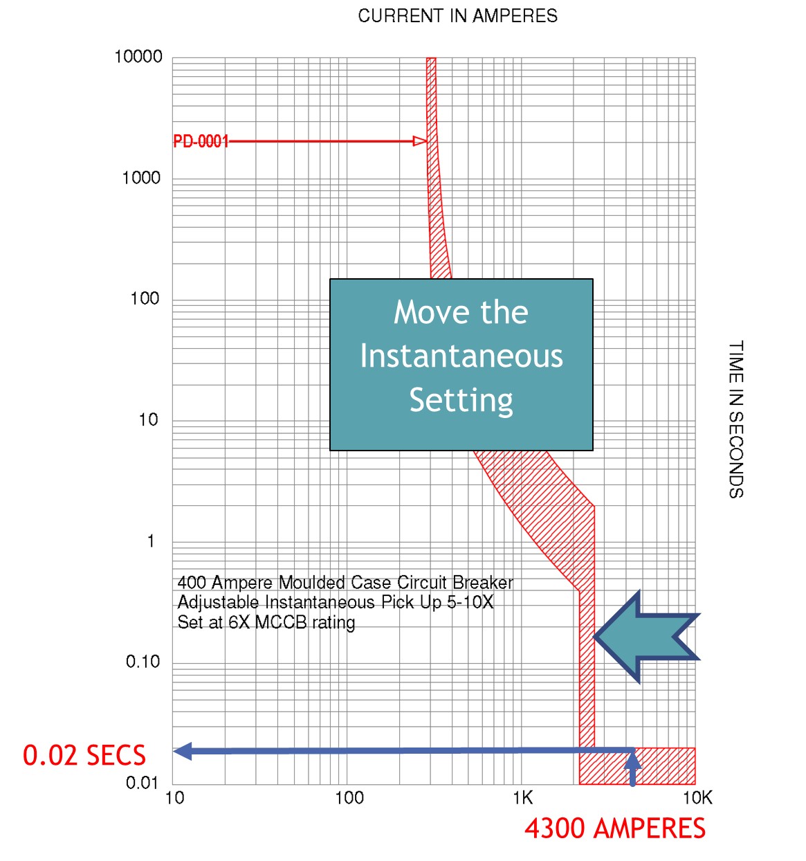
Figure 5.2
My experience is that little effort has been needed to reduce dangerous fault conditions in electrical equipment because of this very simple approach. I remember working on a large technology manufacturing site which had extensive high specification clean room areas. There were 120 panels within the clean room zones that had incident energy levels above 1.2 calories per square centimetre. Working with the Duty Holder, we were able to reduce the incident energy levels below this figure by the adoption of protection alterations. The majority were comparable to the example given above. The other techniques used were to change fuse types or ratings or to reroute the source of supply from a different distribution busbar to reduce the source impedance. Quite simple measures that were inexpensive resulted in an easy to achieve hazard reduction programme for that particular client. Modifying protection settings in order to reduce the risk is what I would term the low hanging fruit of arc flash hazard management.
5.3 Improved Protection Schemes
Protection arrangements should be explored at design stage to prevent or minimise the effects of electrical flashover using schemes such as:
- Fast acting and/or current limiting protection devices
- Maintenance Setting Schemes
- High Impedance Bus Differential
- Low Impedance Bus Differential
- Arc Flash Detection
5.3.1 Current Limiting Protection Devices.
HRC Fuses. High rupturing capacity (HRC) fuses fall into the category of current limiting protection devices. In Europe the NH DIN (Deutsches Institut für Normung or German Institute for Standardization) fuses and the British Standard BS88 fuse are the most popular types of HRC fuses, and both are compliant with IEC 60269-1 standard for low voltage power fuses and both types are current limiting. The fuses are not physically interchangeable, but the characteristic curves are similar. Both NH DIN and BS88 fuses have been around for many years and have a proven reliability record. Indeed, they have remained popular with specifying engineers to this day because of their high fault current handling and minimal energy let-through (I2t). Indeed “British style BS88 fuses are typically found in equipment manufactured in the United Kingdom or British Commonwealth countries. However, North American manufacturers have begun to specify British style fuses particularly in UPS applications at 240V or less to take advantage of their size, performance, and cost benefits”. (Source Cooper Bussmann Fuses)