5.3.2 Maintenance Setting Schemes
Interactions with energised equipment of any description will inevitably lead to some risk. These may be inspections, testing, maintenance, operations or perhaps more intrusive tasks that have been properly assessed and stand the test of reasonableness. A solution may be to retrofit circuit breakers with instantaneous trip units or to temporarily alter the instantaneous settings on circuit breakers. Equipment manufacturers are continually developing better methods to reduce or eliminate the arc flash hazard and have come up with their own solutions to incorporate maintenance settings to the circuit breakers. One such system is described below.
Eaton Electric recently patented a system that they call “Arc flash Reduction Maintenance System(TM)” (ARMS technology) for low voltage moulded and air circuit breakers. It allows for a maintenance mode to be set on the circuit breaker which will in effect provide a lower instantaneous pick-up level via a maintenance switch, which is illuminated when activated. When fitted, it operates independently of the main protection unit and is designed to trip with no intentional delay once the instantaneous threshold has been exceeded.
Arc flash Reduction Maintenance System (ARMS)
The following example, Figure 5.6 shows how they ARMS system is deployed and as can be seen in this example this will reduce the time to trip from 250 milliseconds down to 25 milliseconds. As discussed previously, the incident energy is directly proportional to time so in this case the energy reduction is 90%.
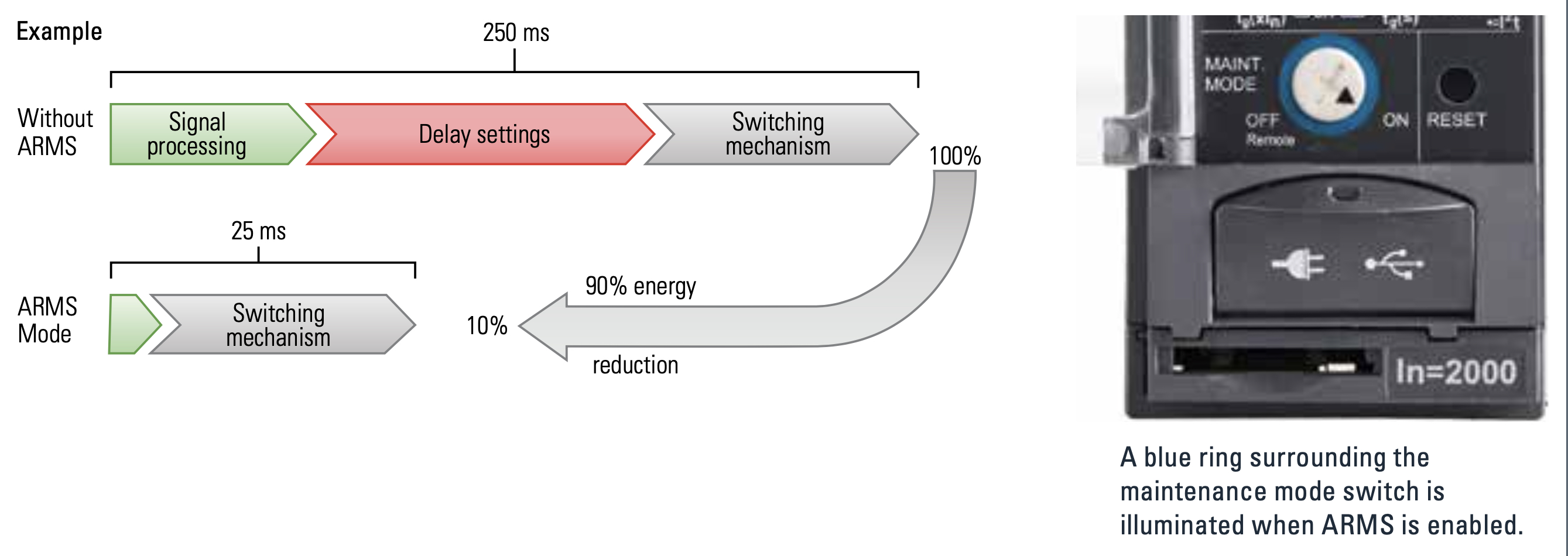
Figure 5.6 Image courtesy of Eaton Electric
The following time current graph in Figure 5.7 shows the normal circuit breaker settings in blue, and the maintenance setting is in red.
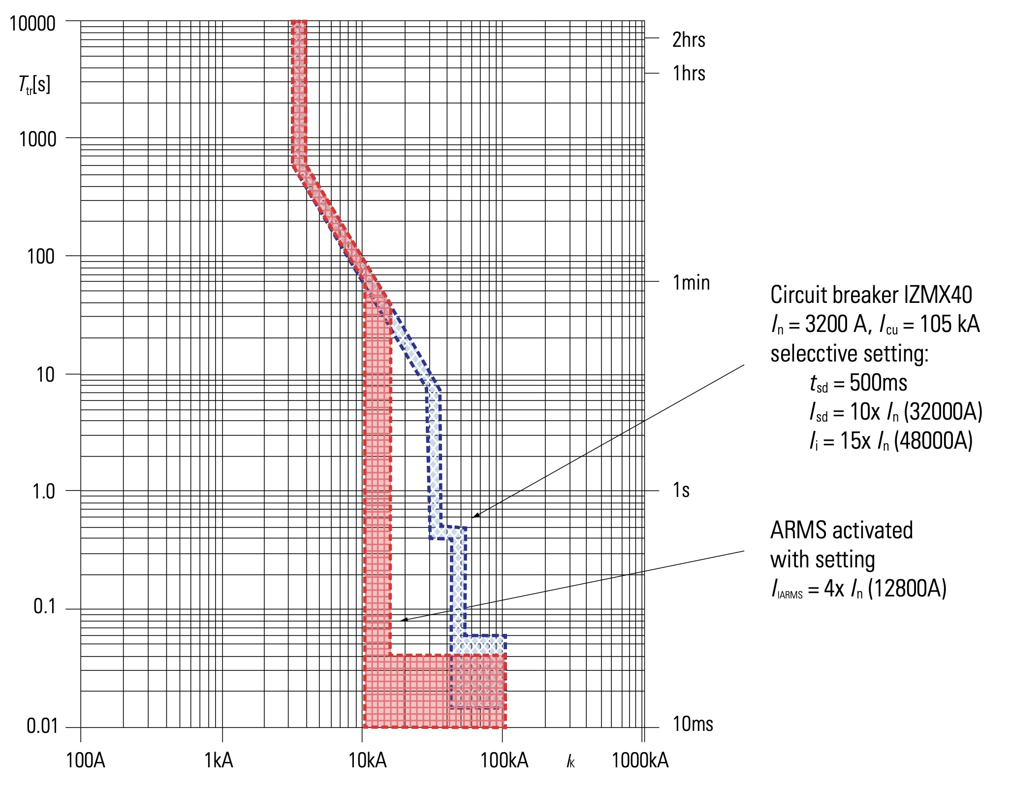
Figure 5.7 Image courtesy of Eaton Electric
As can be seen this effectively reduces the instantaneous pickup level of the circuit breaker in the same way that permanent settings are made to an existing circuit breaker as described in the previous section on protection settings. As with all modifications to protection systems, the selection of one of the reduction settings should be determined and selected by a person who is experienced in power system analysis. I can see that this type of system will grow in popularity but is a solution that is available at design stage only.
5.3.3 High and Low Impedance Bus Differential Protection Schemes
Bus Differential Protection Schemes have been used for many years, predating much of the work of arc flash calculations. They are very reliable but can be expensive. The principle of operation is based upon Kirchhoff’s law which states that the vectoral sum of all currents at a node or bus is equal to zero. Looking at Figure 5.8 the equipment to be protected is the switchboard and associated incoming and outgoing circuit breakers.
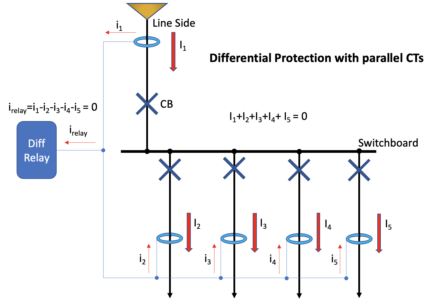
Figure 5.8
The current transformers (CTs) monitor the current entering and leaving the switchboard and for healthy conditions a summation of all the currents will equal zero. If there is a fault on the switchboard, or with any of the circuit breakers, then the relay will detect the differential summated current which will no longer be zero. The relay will quickly trip all of the circuit breakers both incoming and outgoing thus isolating the fault and for arcing faults this can significantly reduce the damage caused. The response time is typically 20 to 30 milliseconds and combined with a typical circuit breaker operating time of 60 milliseconds this will normally give a total clearance time of less than 100 milliseconds. Whilst cost has often put off design engineers from including bus differential schemes in the past, there appears to be a resurgence in the popularity of such schemes in preventing damage from arcing faults in recent years.
There are two types of bus differential schemes, high impedance and low impedance. As the names suggest the high impedance relay presents a high impedance to current flow whereas the low impedance relay does not. The current transformers for the high impedance scheme are simply connected in parallel with the relay. Any difference in current will create a voltage drop across the relay which in turn will trip the circuit breakers included in the scheme. Because of the sensitivity of the relay, it is critical that all the current transformers match by having the same ratios and accuracy. However, one major advantage of the high impedance scheme is scalability. In other words, if another circuit breaker is added, all that is required is a matching current transformer which is simply connected in parallel with the other CTs.
Low impedance relays, on the other hand, have low impedance to current flow from the current transformers. The difference in the installation is that each CT output has to be brought back separately to a discrete input on the relay rather than being connected in parallel with the other CTs. An advantage is that the matching of CTs is no longer critical and it is possible to share the output from CTs for other relays or meters. This makes the low impedance scheme ideal for retrofitting to existing equipment. However, it is not as scalable in that each CT will require its own relay input.