5.4.1 Holistic Approach to Design
I often hear Engineers say that they have designed out the arc flash risk but, what they are really referring to is switchgear design. Designs against arc flash require much more than that. Specific factors that need to be considered when designing out or minimising the risk of arcing are as follows.
Distribution System Philosophy
- Review operating philosophy. For instance, can parallel or very large transformers be avoided?
- Determine the effects of arcing when designing protective equipment.
- Can additional protective or arc reduction devices be installed? As described in this section.
- How is the philosophy for arc prevention communicated? For instance, through design, installation, commissioning and operating manuals.
Switchgear Design
- How will risk assessments be implemented? Such as the identification of hazards and potential failure mechanisms.
- Consider arc detection and suppression.
- Consider internal arc resistance.
- Improved protection devices set to minimise arc energy.
- Consider remote operation.
- Consider dual settings on protective devices.
Operation, Installation and Maintenance
- Commissioning. The feedback loop to design from final commissioning seems so obvious but sadly often overlooked. Tales of transit packaging left inside protection relays or factory settings on circuit breakers years after installation are all too common. Commissioning processes should be informed by correct procedure and manufacturers recommendations.
- Operation and Maintenance. What access to switch gear will maintenance teams require? What level of competence do they have and under what safety rules and processes do they operate?
- Ensure appropriate test, inspection and preventative maintenance processes are in place. These processes should refer to arc flash precautions specifically such as relay setting checks, integrity of insulating shrouding, panels & fastenings and ingress of moisture.
- How will the major risk of unauthorised modifications be prevented?
In Summary, a holistic approach is much more than designing out the arc flash risk through switchgear design. Minimising of the risk of arcing requires whole life care through distribution philosophy, system design, commissioning, maintenance, auditing, and operation. To achieve this requires clarity of policies through leadership and control. Neglectful dilapidation of equipment such as control panels is a tangible indicator that the policy is not working. The diagram in in Figure 5.10 shows the relationship between the Distribution Philosophy, Switchgear Design and Operations and Maintenance.
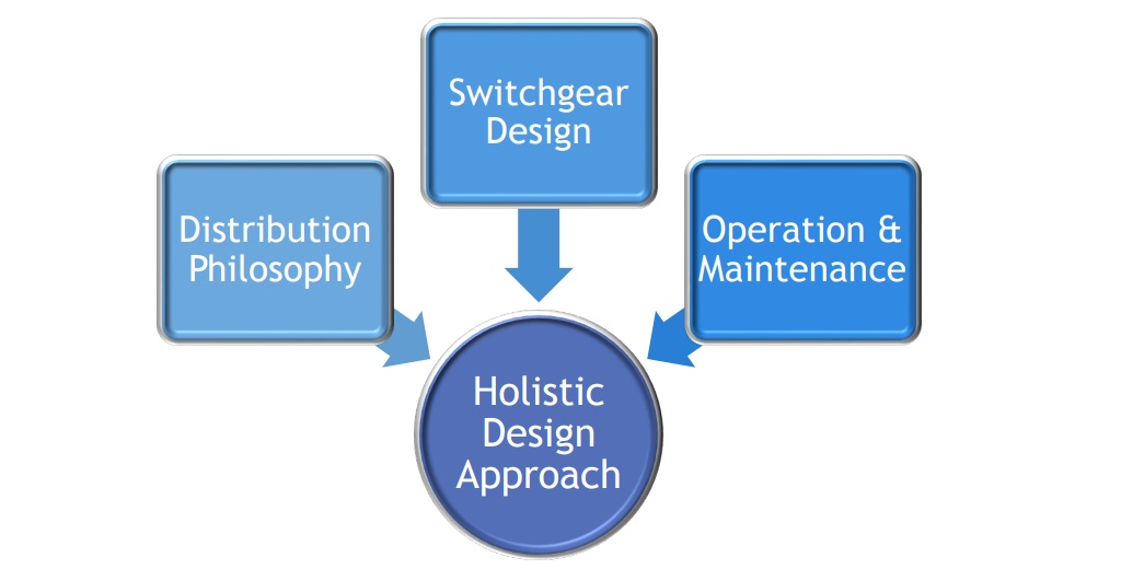
Figure 5.10 The relationship between the Distribution Philosophy, Switchgear Design and Operations and Maintenance.
5.4.2 Design of Low Voltage Switchgear
At low voltage, the design of high-power switchgear is often bespoke in nature and termed as a Power Switchgear and Control Gear Assembly. The standard IEC 61439-2 Power switchgear and control gear assemblies (PSC) applies to such assemblies and stipulates the responsibilities of the end user, the original manufacturer, and the assembly manufacturer.
The assembly manufacturer (manufacturer of the switchgear and control gear assembly) takes responsibility for the completed assembly, but this is often not the original manufacturer of the equipment. They are responsible for the manufacture, conformity to standards, including those of the original manufacturer and routine tests. The user or customer may be represented or assisted by a designer who has, in my view, the greatest responsibility in providing specific design characteristics for the assembly. They will have to provide information such as supply and load characteristics, the environmental conditions and details of operation and maintenance. Dependent upon this data, the final design of the switchgear could vary widely from one assembly to another. There is no specific international standard that covers arc containment in low voltage equipment so it is vitally important that the user (or user’s designer) understands how the specification can help prevent the propagation of an internal fault. There was a time when the risk of internal faults was ignored completely and the term “fault free zone” was used to describe an area of a switchboard that had low risk. Experience shows however, that where there is a current carrying conductor, there is the possibility of a flashover.