In Figure 5.11 you can see the wide difference in specifications for the insulation of busbar systems.
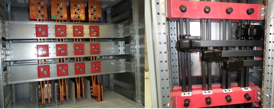
Figure 5.11 Non-Shrouded and Shrouded Bus Bars
IEC 61439-2 also identifies the four main categories of separation: Forms 1, 2, 3 and 4 within assemblies. I have included references to free publications that describe the forms of separation with some detail and clarity. Put simply, the higher the form number, the higher the degree of separation between terminations, functional units and busbars. So, it follows that the higher the number, then the higher the level of safety and the greater the number of tasks that can be carried out whilst the switchgear is energised.
But we cannot rely solely on the design of equipment for safe working and therefore any activities must be covered with risk assessment and safe systems of work. In arriving at which form of separation will be required, reasons for access whilst the equipment is energised will need to be explored. Some reasons may be as follows, although justification is another matter.
- Routine maintenance, where applicable.
- Adjusting settings of overloads and protective devices.
- Resetting Overload or short circuit protective devices.
- Changing fuses.
- Taking instrument readings or measurements.
- Fault finding.
- Re-configuring control circuits.
- Replacing components.
- Terminating power and/or control cables.
- Changing the configuration of outgoing circuits.
One point of contention is how the forms of separation are interpreted for interactions with energised switchgear. For instance, there are references in some manufacturer’s information that state that Form 4 construction is suitable for the connection and disconnection of cables whilst adjacent circuits are live. Whilst the source is named as the BEAMA Guide to Forms of Separation for Low Voltage Switchgear and Control Gear Assemblies to BS EN 61439-2 there is an extremely important caveat given in that document under the section on “Other Considerations Item 7.” This states the following. “Safe working with adjacent equipment energised - Switchboard manufacturers cannot give all embracing assurances for safe working, according to the form of separation with parts of the assembly energised. Specifying a particular form of separation will not guarantee this for any given form number. Effectively this means that where live working is being contemplated, a risk assessment and judgement must be made for every situation by the Duty Holder.”
To illustrate this point, compliance with IEC 61439-2, Power switchgear and control gear assemblies (PSC) requires that the separation between functional units, separate compartments or enclosed protected spaces is attained by either one or more of the following conditions:
- Protection against contact with hazardous parts. The degree of protection shall be at least IPXXB.
- Protection against the passage of solid foreign bodies. The degree of protection shall be at least IP2X.
Both methods are similar and often referred to as “finger safe” although it is just method IPXXB that uses a test finger to prove compliance. In either case, a 12mm gap will be acceptable and this is enough to allow the passage of some tools, fastenings and cable armour wires. The main message here is to be aware that equipment design alone does not ensure safe working on energised equipment. I have referenced forms of separation in my chapter on Myths and Mistakes later and give examples where misinterpretation of design criteria has led to accidents in Form 4 equipment which is the specification for higher forms of separation.
For many of the reasons for access to low voltage power switchgear and control gear assemblies, safety can be enhanced at design stage by reducing the voltage of all controls preferably to 24 volts DC. In addition, by moving them to separate cabinets or enclosures there is a reduced requirement for working on or near energised circuits.
5.4.3 Low Voltage Switchgear and Control Gear Assemblies, Internal Arc Protection
Switchgear that is termed as arc resistant uses various methods to contain or redirect the arc away from the operator or from causing damage to the equipment or surrounding environment. Typically, such equipment will use systems such as venting or containing the arc and international standards are being refined constantly to reflect the progress in this regard.
Internal arcs within switchgear are not common but the severity can be catastrophic. Causes of internal arcs can be the result of incorrect maintenance, vermin, ingress of water or dust, dielectric faults to insulators, terminations, current and voltage transformers. Design issues such as overstressing of functional units and susceptibility to overvoltage and transients are also contributory factors. Not forgetting good old wear and tear and ageing.