Do the detective work. Reference to current drawings (taking care to allow for inaccuracies) and records alongside circuit and equipment labelling is a good start. Consult the electrical system owner or experienced maintenance crews whenever possible. Use physical inspection such as tracing out circuits to determine the correct isolation points relating to the work required. If the equipment is a distribution board, identify an outgoing load that is non-essential such as a lighting circuit. When switching and verifying it can be another step in positively identifying the points of isolation by observing simultaneous extinguishing of lighting circuits through the switching operation. A similar approach can be made with panel control lamps if the piece of equipment is a power switchgear and control gear assembly. This may sound like stating the blindingly obvious, but believe me, having audited individuals whilst they are undertaking isolation procedures, it surprises me how often these simple steps are omitted.
Testing because of inadequate records. Where testing is carried out to locate circuits due to inadequate records or circuit labelling then this should be considered as live working.
Unauthorised modifications or circuits. Finally, always be open to the possibility that there may be unauthorised feeders and/or modification that are not detailed in circuit diagrams and records.
STEP 3. DISCONNECT.
The usual means of disconnection of circuits at low voltage are:
- the withdrawal of fuses and/or links
- operation of miniature and moulded circuit breakers
- opening and isolation of air circuit breakers
- opening of switch fuses
- opening of isolators
- physical disconnection of conductors
- withdrawal of a plug from the socket outlet
- third party isolation via a utility company
Notes.
Reduce connected load. Before operating isolators or removing fuses reduce as much of the connected load as possible.
Physical disconnection of conductors. This can only to be carried out dead, but this may be the only option in certain circumstances. For instance, if the disconnection device is not rated as an isolator or that the point of isolation cannot be secured with a padlock or other device.
Visual inspection of isolator blades. Make sure, wherever possible and visible, to check and to ensure that all the blades have opened in switch fuses and isolators. I have seen it first-hand where the operating bar has broken leaving a blade in place and energised. I also remember a recall notice for a popular brand of devices for that same fault.
Circuit Breakers in the tripped position. Miniature and moulded circuit breakers can never be used for isolation in the “tripped” only position. This is one of the mistakes that led to the incident mentioned in my introduction to the guide.
Storage Devices. Ensure that storage devices such as capacitors are fully discharged. Capacitors can store huge amounts of energy that can cause a serious blast hazard. If you have concerns about the capacitors, I can recommend the 2021 version of NFPA 70E which has the subject covered in some detail in Informative Index R. It is free to view, and I have given details of the document including caveats in Chapter 16: Rules, Codes and Legislation.
STEP 4. VERIFY INCLUDING TESTING.
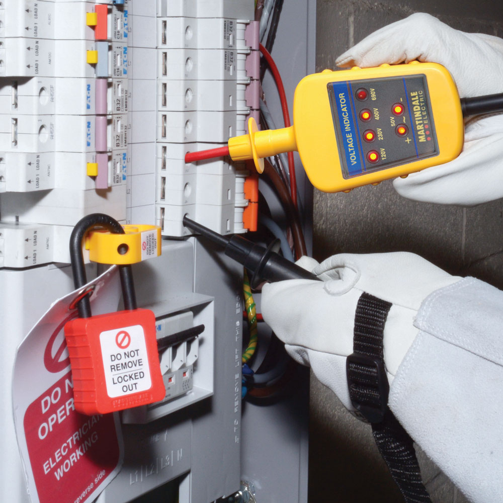
Figure 6.8 Image courtesy of Martindale Electric
The whole point of steps one, two and three is that verification will be on dead conductors. We have already reduced the risk from arc flash if these steps have been carried out diligently. But should there still be a residual risk the following will serve to reduce it to as close to zero as possible. Know what the incident energy level is and take a decision on how to proceed. Decisions should be based upon risk assessment especially in respect of whether to deploy PPE or not. There is a good deal of guidance on this elsewhere in the guide especially in Chapter 4: Prediction and Chapter 7: Protection but what I would suggest is a minimum of hand protection regardless of the incident energy levels for low voltage testing. So, in other words, insulating gloves and leather over gloves.
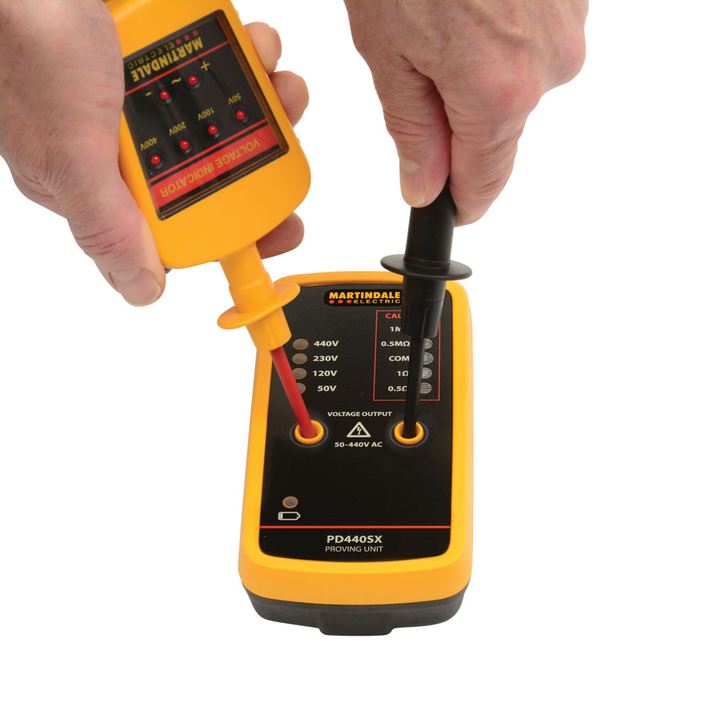
Figure 6.9 Image courtesy of Martindale Electric
In Chapter 12: Myths and Mistakes, I give an example of an electrician who was hospitalised after suffering burns to his hand. I put objections to wearing gloves for testing in the same category as not wearing a mask. There may be some inconvenience, but loss of dexterity is in my view, overblown.
Use the correct equipment. I would suggest that multi-meters should not be used for testing for dead. Correctly calibrated proprietary voltage indicators, with fused leads and matching test units (Figure 6.9) should be used to check for the absence of voltage.