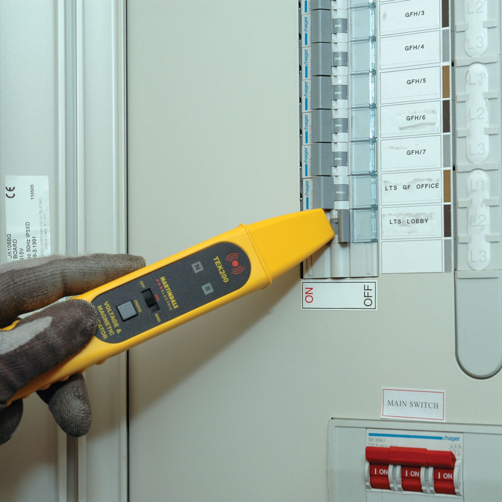
Figure 6.10 Image courtesy of Martindale Electric
Non-contact voltage indicators (Figure 6.10) are a good idea providing that they are NOT relied upon for the final proof of dead conductors. Look for devices that have self-proving circuits and can give an indication if they are faulty. They may obviate the need for PPE for instance as used as part of the risk assessment given earlier. In addition, they can be used to look for rogue circuits. For example, in a control panel or composite switchboard, cables may have been drawn in that are supplied from another source. The panel may have been used as a trunking so there may be insulated but live cables in the working area. Make sure that you fully understand what the non-contact voltage indicators are capable of from the manufacturer’s data and instructions especially voltage ranges.
Test ALL Poles of Supply. The arc flash incident mentioned in the introduction was a classic case of not testing all poles of supply between current carrying conductors and then each current carrying conductor and earth including neutrals. There was a failure to test to earth which would have detected that the red phase contact on the controlling moulded case circuit breaker was welded closed whilst the other two phases were open.
Test the lowest rated circuits first. For instance, if the piece of equipment is a power switchgear and control gear assembly then test at the control fuses or an outgoing protective device.
Lower upstream device settings. If the incident energy levels are still very high, consider lowering the upstream protection settings. This does need care to make sure that appropriate settings are reapplied upon completion.
STEP 5. SECURE.
ALL practical steps to prevent re-energisation should be taken with the goal that there is no risk that circuit conductors and electrical equipment can be made live, whilst work is in progress. Some measures can include:
- The retention of fuses, links and withdrawable circuit breakers and application of lockable blanks and retention of keys.
- Disconnection of circuit conductors.
- Locking off points of isolation such as circuit breakers, isolators and the retention of keys.
- Removal and retention of castell keys where these mechanically interlock with switches or circuit breakers ensuring that spare keys are not available.
- Specially designed locked facilities, e.g., lockout boxes.
- Use of properly designed earthing devices.
Earthing. Applying circuit main earths where they are available is mandatory. For other situations this is an option for the designated person to consider bearing in mind that control needs to be exercised in their application and removal.
Lock and Label Points of Isolation. Secure all points isolation using a lock and unique key. Post caution notices at all points of isolation and also on any earths that have been applied. Make sure that all notices are removed on completion.
Labelling adjacent equipment. If there is live equipment in the vicinity that could be mistaken for the equipment to be worked upon, then apply a label. A “danger live” notice will usually suffice, the presence of which should be noted on any permits that are in use and they must be removed on completion.
Third Party Isolations. An isolation from a third party such as a utility company, needs to be thought through carefully as the designated person for securing the isolation should always have control. There are various ways in which this is achieved, and this is how I have gone about it in the past. Firstly, try to accompany the person from the third party who is undertaking the isolation and be assured from discussion and observation that this is the correct point of isolation. Secondly, ask that person to accept a means of securing that point of isolation such as a lockout box with your lock on it or a multi hasp device. Finally, ask for a written statement of the isolation. This will not be a permit to work as the third party is not responsible for your working party (there could be other sources of supply outside his/her control), and it is likely to be an isolation and earthing certificate. Most utility engineers that I have worked with will cooperate in assisting and assuring you in order to help you to fulfil your responsibility to set up a safe system of work.
Generators. Work on generating and motor driven plant is not to be carried out unless the machine concerned has been securely isolated from all possible rotational driving forces. Particular attention is to be given to the isolation of the auxiliary circuits, controlling the automatic start sequence of any prime mover associated with a generator.
Distance. Finally, putting any distance between the test site and the person is beneficial because of the exponential reduction of incident energy as discussed previously.