The calculators and tools that are available with this guide will allow you to quickly determine which circuits are below 1.2 cal/cm2 so the first three parts of our risk assessment can be completed for the arc flash hazard. In a generic tiered approach, I have grouped the above calculators and tools as tier 1, 2 and 3. In the following pyramid diagram, Figure 10.1, these groups are listed and at the base are the tier 3 circuits which are the most plentiful in most industrial and commercial facilities. As you can see, the only information that will be required is the type and size of the upstream protection and the minimum prospective fault current level. Tier 2 circuits need actual fault level only and finally, at the top of the pyramid, the actual fault level and a time current curve will be required to return an accurate prediction of arcing current and incident energy. Chapter 14: Hazard and Severity Calculators explains all the tools in detail.
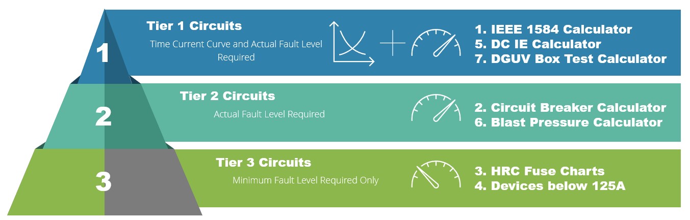
Figure 10.1 Three tier calculator approach
Tier 3 Circuits – Are the low voltage circuits where the upstream device is known but there is no need for a time current curve. All that will be required is the minimum prospective fault current at the equipment to be worked upon. Circuits where the incident energy is below 1.2 cal/cm2 can be quickly determined as well as those circuits where there is a dangerous hazard level. These conditions are given in the protective devices that are listed in the calculators and tools that accompany this guide. From experience, you may not know what the actual prospective fault current is, but what is usually apparent is what the fault level is not. For instance, if the named range is 2000 amperes and below, a skilled person would be able to determine the likelihood of that being the actual fault level at the equipment. For other instances, there is a prospective short circuit current calculator which accompanies this guide.
Tier 2 Circuits – Are similar to tier 3 circuits insomuch as they are low voltage where the upstream device is known but there is no need for a time current curve. In this case, what will be required is the actual prospective short circuit current at the equipment to be worked upon. This is providing that the fault level does not exceed the capability of the device.
Furthermore, the protective devices are circuit breakers but are not listed in the calculators that accompany tier 3 circuits detailed above. In the tier 2 there is a circuit breaker calculator for ACBs and MCCBs which will allow you to determine an incident energy level based upon the circuit breaker characteristics. The calculator tool works on the basis of a device instantaneous characteristic and produces an actual incident energy level. From this information parts 4 and 5 of our risk assessment process given previously, can be followed which are; “considering if the risk can be eliminated; and if not, making a judgement on whether further measures to prevent or reduce the risk needs to be introduced”.
Tier 1 Circuits - will require details of the time current characteristic curve for the protective device as well as the actual prospective short circuit current at the equipment. The toolbox has an accurate calculator based upon the IEEE 1584 Guide for Performing Arc Flash Hazard Calculations, to determine the incident energy. It also incorporates motor fault level contributions if required.
The above calculators will allow you to recognise extreme danger as part of your risk assessment process and the effort is not too onerous in terms of applying the models. For many service providers it could confirm that for the majority of their operations, the arc flash hazard is not of a high order. It will allow them to apply a rule of exceptions to their safety procedures. In other words, be able to highlight extreme danger which will not be the norm for much of their day-to-day activities. For those service providers who are working routinely on high energy circuits, this will allow a review of their activities to make sure that they are effectively managing the arc flash risk.
There is also a prospective short circuit current calculator and additional tools to plot time current curves for IDMT relays and European style (BS88 and DIN) fuses.
10.2.2 Prevention.
Prevention must be the fundamental safety principle for the management of arc flash risk. Please refer to Chapter 5: Prevention & Minimisation which gives a comprehensive view of how the arc flash hazard can be prevented from causing harm. The following highlights those prevention issues which the service provider may need to focus upon.
Dead Working. We must always seek to design out, eliminate or remove the hazard at its source and in most cases, this means dead working. The pressure for working on equipment that is still live is sometimes driven by the client and I give an example of this in my Chapter 12: Myths and Mistakes. Without a doubt, the best method of managing the arc flash hazard is dead working and the service provider must resist the pressure to do otherwise wherever possible.
To work dead, the electricity supply must be isolated in such a way that it cannot be reconnected, or inadvertently become live again, for the duration of the work. As a minimum, this will include the positive identification of all possible supply sources, the opening and locking of suitable isolation points by personal padlocks and for the proving dead at the point of work. Earthing down of current carrying conductors will be a requirement of high voltage installations. As a competent service provider, having full and exclusive control of the process would help but that is not always possible or desirable. For instance, isolation of circuits may introduce other hazards elsewhere in the facility, as an example, circuits in a hospital. Whilst exclusive control of the process may not be possible, the goal must be to have control of the point of isolation or isolations.