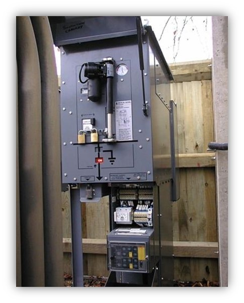
Figure 5.16 Remote circuit breaker actuator unit
As you can see, this looks rather crude, made up of rope and pulleys, but it was very effective at giving good distance between the operator and in this example an 11kV oil filled fused switch. Electrically powered actuators were developed for the operation of manual switchgear which could be retrofitted if necessary. As you can see from Figure 5.16, this is fitted to an outdoor SF6 circuit breaker. The drive was to reduce downtime on electrical distribution systems but would add to safety by removing the individual from the direct operation of the switchgear.
There is a growing demand on switchgear manufacturers to provide remote operation at design stage. In Figure 5.17 you can see an example of a low voltage switch board designed and manufactured as a bespoke factory-built assembly which was destined for a European client. Theearlier rope and pulleys have been replaced with a remote switching unit with an umbilical cord.
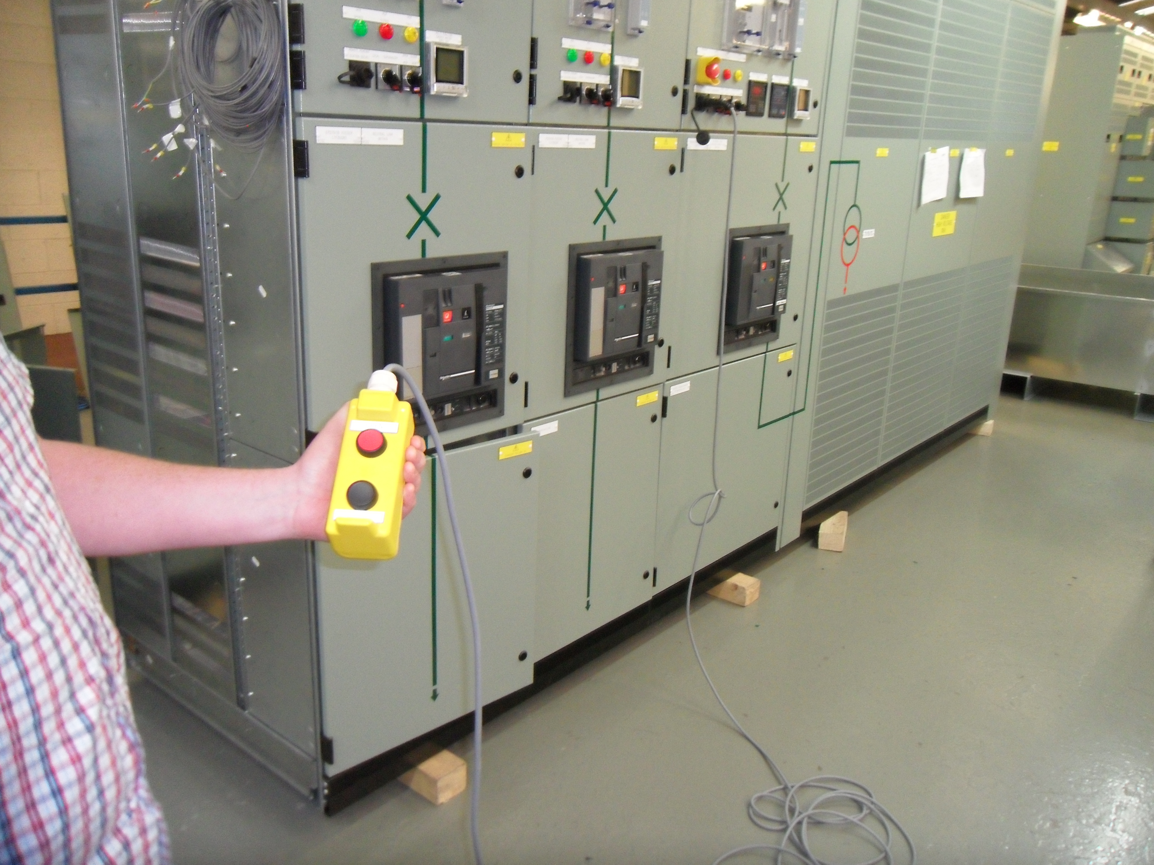
Figure 5.17 Low voltage switchboard
The greatest risk to operators of electrical switchgear tends to be in racking operations. This is where a removable circuit breaker is racked out or racked into the fixed portion of switchgear onto busbar spouts. The operation accounts for the deaths of two engineers that I am personally aware of at a power station where I subsequently provided an arc flash study. Most large manufacturers of switchgear are providing remote racking solutions nowadays for new switchgear. There is also demand for remote circuit breaker racking devices and remote switch actuators, operators and kits for older and even obsolete switchgear and independent companies have developed solutions over a number of years. Figure 5.18 shows a rotary remote circuit breaker racking system which is fairly universal and there are fitments that allow for the horizontal or vertical operation of circuit breaker trucks at low and medium voltages.

Figure 5.18 Remote circuit breaker racking units. Image courtesy of CBS ArcSafe
5.7 Partial Discharge Testing
Arc flash events in medium voltage equipment are often preceded by partial discharge. It is defined as a discharge that only bridges part of the space between two conducting elements and is due to voids, cracks and inclusions within the insulation. Partial discharge in electrical switchgear and cables occurs because of ageing from thermal and mechanical stresses sometimes brought on by heat, humidity and other external influences. Left undetected, partial discharge can lead to catastrophic failure and electrical arc flashover. Prevention of a flashover due to partial discharge is therefore a worth looking at as an overall strategy.
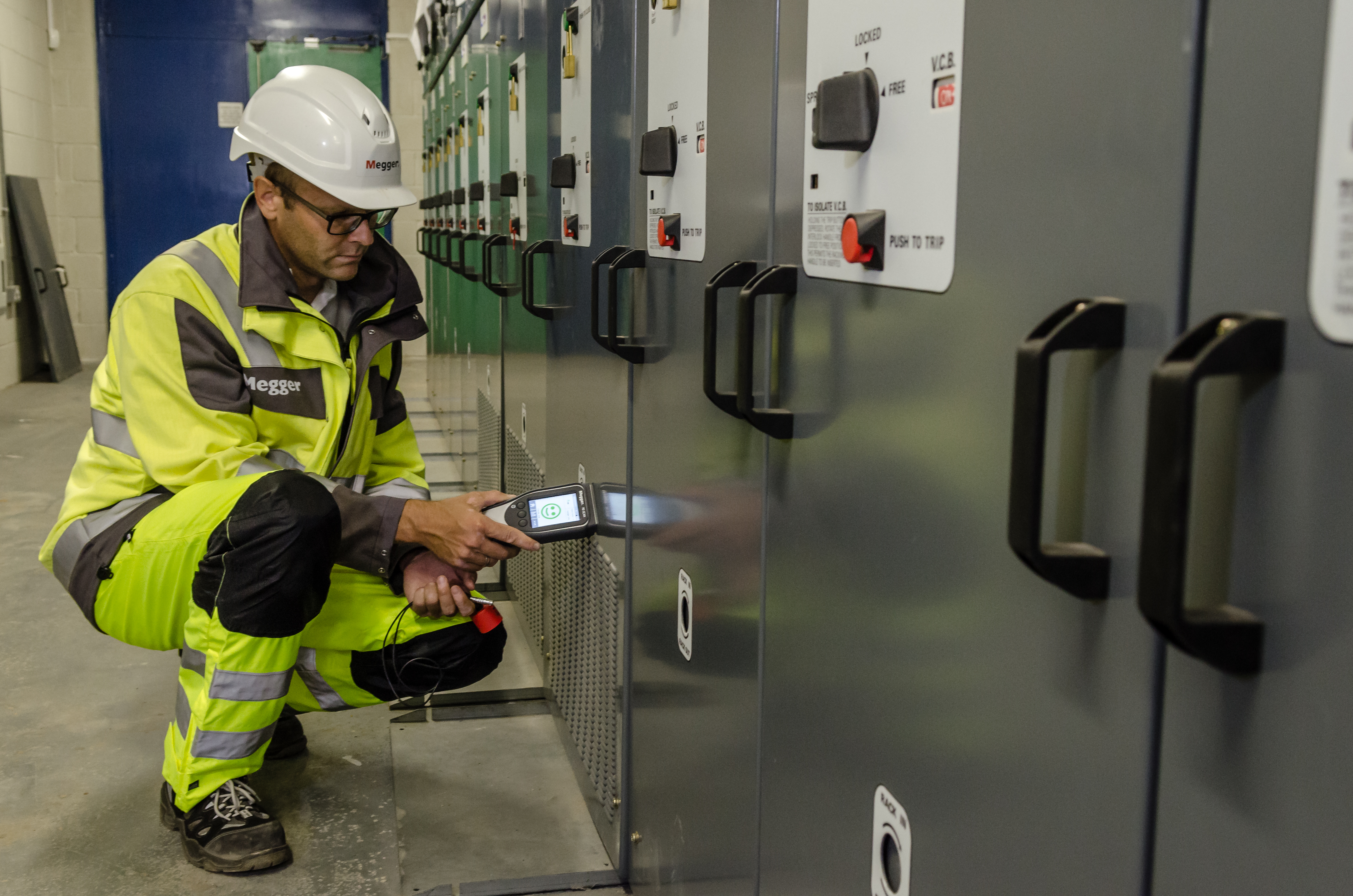
Figure 5.19 Image courtesy of Megger Ltd
There is a good deal of research that suggests over 80% of all failures in high voltage electrical equipment is a result of partial discharge, so early detection can prevent injury due to catastrophic events and the consequential losses of power failure. Partial discharge presents as heat at the source of the discharge, ultraviolet and visible corona, electromagnetic radiation, ultrasonic radiation and audible sound.
The following methods can be used to detect partial discharge (PD) and provide condition monitoring of PD levels over time to warn of impending failure in high voltage cables, switchgear, transformers, generators and motors.
5.7.1 Electromagnetic Methods.
Electromagnetic (radio) waves at around 200+ MHz are produced from the site of the discharge which induce small currents in surrounding metalwork. The high frequency voltages that are produced are known as Transient Earth Voltages (TEV) and can be picked up using a capacitive probe and handheld detector or by UHF reception ultrasonic and audio microphones.
5.7.2 Acoustic Methods.
Partial discharge causes sound which is both audible and ultrasound (which is outside the audio range). This will present itself as a fizzing sound and can be picked up using sensitive microphones.
5.7.3 Thermal and Optical Methods.
Partial discharge will create heat which can be picked up using thermal imaging. PD will also create ultraviolet light due to the ionisation process which can be picked up by line of sight. However, most industrial indoor enclosed high voltage equipment would not make these methods a viable solution.
5.7.4 Oil Diagnosis.
Although increasing amounts of electrical equipment are moving away from using oil as an insulating/cooling or arc quenching medium, there are large amounts out there and will be for some time to come. Oil sampling and dissolved gas analysis will, over time, monitor the condition of insulating oil in equipment and may indicate serious impending breakdown due to internal arcing and or partial discharge activity. Tests on transformers should be carried out annually in my view as results of organic acidity, dielectric strength and moisture content may indicate the conditions in which the equipment will deteriorate more quickly which may lead to partial discharge.
Although partial discharge testing has been used in low voltage systems, detection is generally restricted to equipment operating at voltages greater than 3kV.
5.7.5 Portable PD Testers.
Portable partial discharge testers have come on a long way and require much less expertise and technical knowledge to operate. Whilst they will give a traffic light type output, they are very useful as part of dynamic risk assessments and also to signal where further investigation will be required. They are handheld and are capable of picking up the characteristic partial discharge noise, vibrations and RF radiation through a TEV (transient earth voltages) sensor.
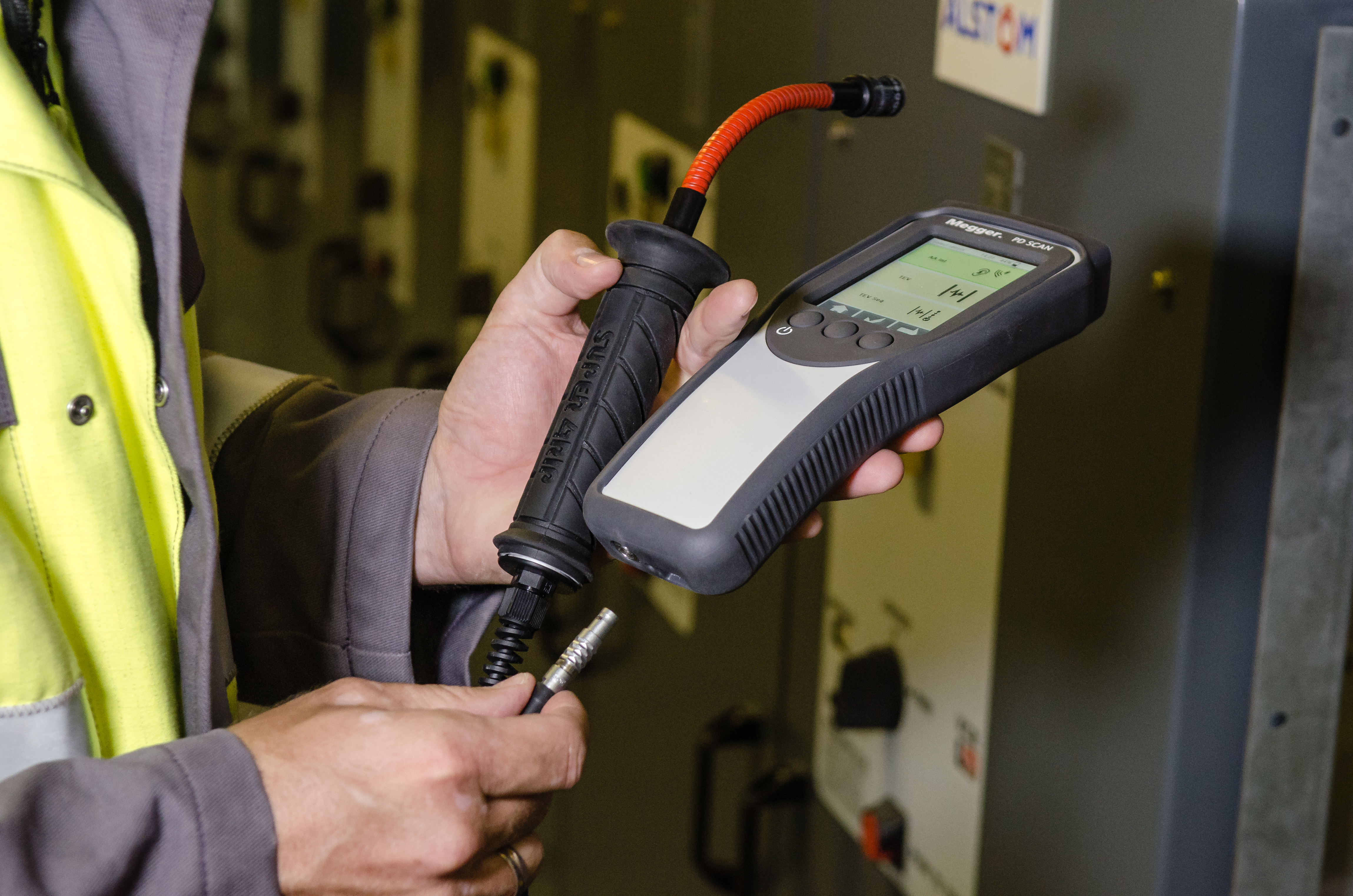
Figure 5.20 Image courtesy of Megger Ltd
- Prevention must be the fundamental safety principle for the management of arc flash hazard.
- It is a legal requirement to design out, eliminate or remove the hazard at its source.
- Simple modifications protection settings can account for 90% of risk reduction techniques.
- New technologies in switchgear design can vastly reduce the risk and prevent injury.
- Reducing disconnection time and increasing distance are key risk control measures.